The construction guidelines offered in the preceding sections must be supplemented by calculation of the necessary cross-sections in practice. Because the packaging is custom-built, i.e. the dimensions of the packaging are chosen to match the dimensions and weights of the packaged goods, there is a wide variety of possible dimensions and gross weights and hence, a wide variety of solutions also. In order to provide users of this guideline with assistance in dimensioning boxes/crates, this section provides guideline dimensions for the load-bearing components for a range of different size classes of boxes/crates that occur frequently in practice. These dimensions only apply under the conditions stated. If the real conditions are different, calculations are necessary. The cross-sections listed here are determined on the basis of DIN 1052 "Design of timber structures – General rules and rules for buildings" issued in August 2004 and the calculation method derived from this by the BFSV (Institute for Consulting, Research, System Planning and Packaging Development and Testing). The conditions under which the recommended dimensions apply are as follows:
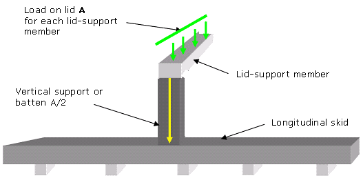
Figure 70: Box/crate components subject to loads during transport and handling Longitudinal skid: The loads on the longitudinal skids during transport and storage are primarily bending loads, in particular when the slinging points for the crane or forklift are not directly below the points at which the packaged goods exert forces (rigid goods). The longitudinal skids are always subject to bending stresses in the case of non-rigid packaged goods. Because the dimensions of the packaged goods and the points of contact on the longitudinal skids can vary considerably, these values must be considered as variable, with the result that the range of possible solutions is equally varied. The cross-section dimensions listed in the following table therefore apply exclusively under the special conditions named. The following load scenarios form the basis for the example cross-sections calculated. Any deviation from the dimensions given will lead to different results. Rigid packaged goods: 4 contact points, 2 contact points per horizontal skid 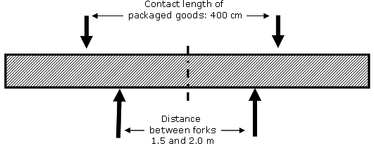
Non-rigid packaged goods: along entire length of skid 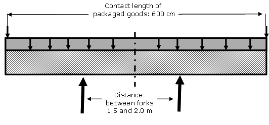
Figure 71: Load scenarios when the longitudinal skids are under
Rigid packaged goods: 4 contact points, 2 contact points per horizontal skid 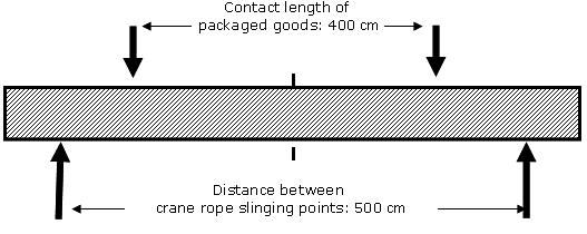
Non-rigid packaged goods: along entire length of skid 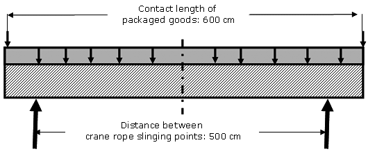
Figure 72: Schematic diagram of loads arising from slinging with distances Lid-support members, vertical side-wall battens / vertical supports: Some general statements with regard to dimensioning can be made for these two load-bearing components on the basis of the defined load on the lid and the figures for loads arising during transport. It is assumed that ten lid-support members will be used across a box length of 6 m, along with the corresponding vertical supports in the side walls. Dimensioning in relation to volume and gross weight Conditions:
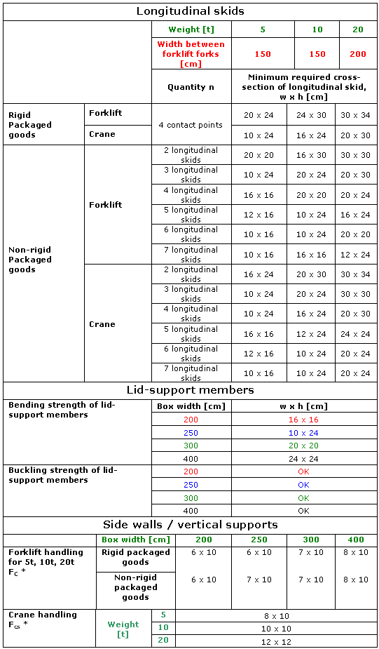 It must be assumed that the critical factor when supporting lid-support members is the buckling resistance of the vertical side-wall elements. In other words, if this value is not exceeded (and has therefore been calculated), the compressive force at the contact surface between the lid-support member and the vertical support/batten is within the admissible range. Conditions:
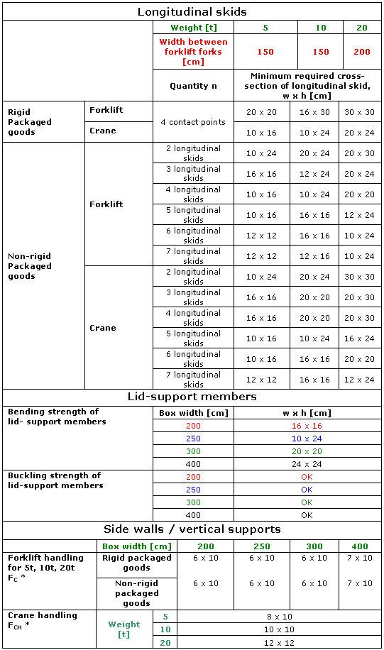 * Notes on both tables:
During transport, the forces FC arising from cargo being stacked on top of the box are conducted into the side walls / vertical supports. During handling (crane), the weight of the packaged goods and the positioning of the ropes (angle = 60°) can result in higher compressive forces FCH on the side walls / vertical supports in the region of the slinging points (4 lid-support members). These higher values are indicated in the table in each case. The cross-sections calculated only apply to the given case dimensions, weight and slinging points. In the event of different box dimensions, weights and slinging points, new values must be calculated. |
| Top of pageContents |
