
The frame members and cladding of the side walls and end walls conduct the stacking forces into the floor, and must provide sufficient resistance against shifting caused by horizontal acceleration forces. They are subject to stress as a result of:
The fundamental design of side walls and end walls and their components are shown in Figure 57: 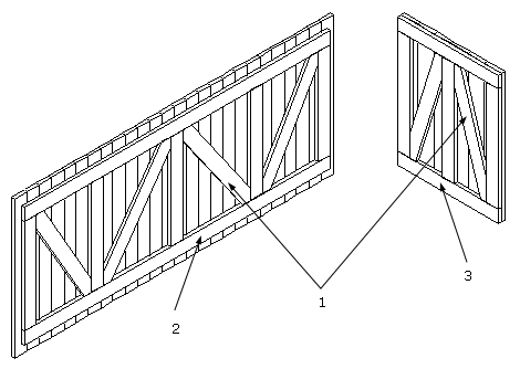
Figure 57: Components of the side walls and end walls of a cut-lumber box Key (Figure 57):
Boards used for cladding should always be arranged vertically, as this provides greater stability (exception: long, narrow, low boxes for long goods). To improve the resistance of the box construction to the shear loads and stacking forces, the end walls and side walls are constructed using transverse, longitudinal, vertical and diagonal battens. Each side or end wall requires one upper and one lower longitudinal or transverse batten respectively. One vertical batten should be present on the end wall per longitudinal skid. The number of vertical battens attached to the side wall depends on the length of the box, but the distance between them should not exceed 100 cm. Table 13 shows the number of vertical battens required:
Table 13: Number of vertical battens required depending on the length of the box The arrangement of battens on the walls of boxes clad with sheet material is the same. No diagonal members are required, as the sheet materials have a sufficiently high shearing modulus. The joints between the sheet material should wherever possible be arranged in such a way that they are covered by the battens. If this is not the case, additional battens must be used to cover them. In the case of boxes and crates which will have other cargo stacked on top of them, the battens must have a 50 x 100 mm cross-section in order to ensure that the lid-support members are securely supported during handling and transportation and are able to withstand the compressive forces arising from stacking. Another option is to increase the contact surface of the lid-support members by adding a further framework of battens to the side walls (see Figure 58): 
Figure 58: Support for the lid-support members in the form of In the case of boxes with large lid areas (high stacking pressure) and boxes higher than 2.5 m (large effective length) that are to have cargo stacked on them, vertical supports must always be provided for the lid-support members. The distance between these vertical supports is determined by the number of lid-support members required (see section 6.3.3). It is necessary to determine the cross-section of the vertical support elements by calculation. See the calculation examples / table in section 6.4. 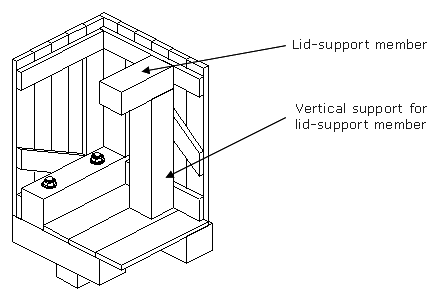
Figure 59: Arrangement of an additional vertical support Boxes wider than 200 cm that will not have other cargo stacked on top of them during transportation and storage do not require any special wide, vertical battens or vertical supports. In this event, the lid-support members can rest on the upper, horizontal side wall battens. See Figure 60: 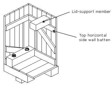
Figure 60: Lid-support member resting on upper, horizontal side wall batten Diagonal battens: Diagonal battens are required if the internal height of the cut-lumber box / crate is greater than 150 cm. The following schematic diagrams show a possible arrangement for the diagonal battens and possible subdivisions of the wall areas. Diagonal battens must be well fitted into the batten framework of the walls: 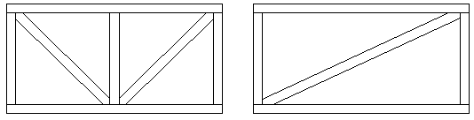
Figure 61: 1 field, max. size: 300 cm length · 150 cm height 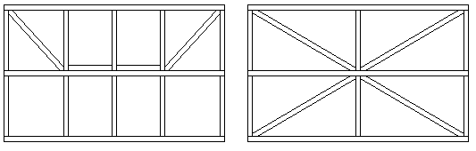
Figure 62: 2 fields long / 2 fields high, max. size: 500 cm length · 250 cm height 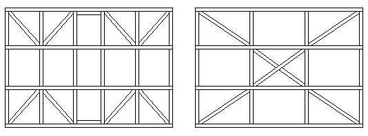
Figure 63: 3 fields long and 3 fields high, max. size: 700 cm length · 350 cm height The overall stability of the box/crate is impacted if important components do not meet the assumed or actual requirements with respect to the load assumptions made in this guideline. This means that the battens used for butt or corner joints must be carefully selected with respect to their suitability. Edge boards must not be narrower than 10 cm, and other boards must not be narrower than 8 cm. The thickness of battens for the side and end walls of boxes and crates will generally be 24 mm. To provide greater stability to the corner joint between the side wall and end wall, the side walls should be fitted with end battens that directly abut the end walls. 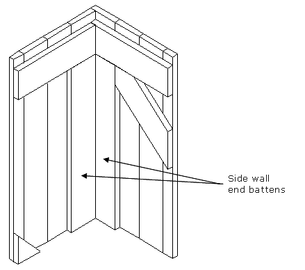
Figure 64: Arrangement of the side battens in the corners The same principles with respect to the use of battens on the walls of boxes with cut-lumber cladding also apply to the walls of boxes with plywood or OSB cladding. Battens must always be placed behind the joints between the sheets. No diagonal members are required, as the sheet materials have a sufficiently high shearing modulus. The inside walls of boxes with cut-lumber cladding can be lined with a barrier layer of kraft paper in order to cover the gaps between the individual boards. This layer is attached between the cladding and the batten framework. 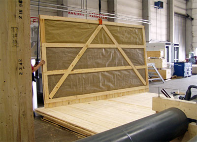
Figure 65: Side wall lined with a barrier layer |
| Top of pageContents |