
6.3.1 Floor element The floor must be seen as the most important element of a box/crate, as it has to withstand both the weight of the packed goods acting downwards and the opposing upward forces resulting from the use of forklifts and ropes/chains. 
Figure 51: Components of a floor element with transverse skids Key (Figure 51):
The floor must provide lifting facilities for cranes and forklifts that take account of the subsequent location of the center of gravity. In particular, steps must be taken to ensure that sufficient clearance is provided to allow the forks of ground conveyors to be inserted. In the case of boxes for heavy cargo (as of 1,000 kg gross weight), this clearance must be at least 12 cm. This is generally achieved by arranging transverse skids under the floor of the box. 
Figure 52: Floor construction with transverse skids Another option to allow the forks of ground conveyors to be inserted is the use of runners (see Figure 53 below). These are always advantageous if boxes/crates must be pushed lengthwise, for instance when stuffing a container, see section 6.6.1. 
Figure 53: Runners with fork insertion aperture; center of gravity in the middle If the center of gravity is not in the middle, runners have the advantage that they can be placed in such a way that the center of gravity of the package is always between the slinging points and the ground conveyors can always insert the forks in the correct position. 
Figure 54: Runners arranged to compensate for the offset center of gravity Whether the center of gravity is offset or central, runners must be interrupted in such a way that the fork insertion apertures are symmetrical with respect to the center of gravity. This also applies to the slinging points for ropes, belts or chains. At the ends of the boxes, the runners must be stepped and chamfered in such a way that slinging equipment such as ropes, belts or chains can be attached safely. The apertures in the runners to accommodate the forks of ground conveyors can have the following dimensions depending on the gross weight: 
Figure 55: Distance between the runners for the In the case of boxes/crates for heavy cargoes, the narrow ends of the floors must be fitted with internal end beans that are bolted to the longitudinal skids. In the case of boxes which cannot be lifted by forklift truck, care must be taken to ensure that no insertion apertures are provided, for instance by ensuring that the runners are not interrupted. It may also be advantageous to close off the ends of boxes to ensure that they cannot be picked up by ground conveyors. This is especially true of boxes that are to be transported in containers. 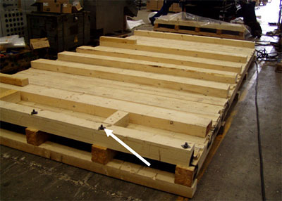
Figure 56: End beams located at the ends of the floor The distance between the individual longitudinal skids should not be greater than 80 cm. Longitudinal skids should always be placed on edge to ensure bending strength. Insofar as there are no particular requirements with respect to securing the packaged goods to the floor, the number of longitudinal skids should be chosen on the basis of Table 12:
Table 12: Minimum number of longitudinal skids depending on the floor width In the case of heavy cargoes that require a correspondingly stable floor construction, it is also possible to construct the floor from a combination of steel and wood for economic reasons. This is always the case if calculations result in extremely large lumber cross-sections for the longitudinal skids. |
|||||||||||||||||||||||||
| Top of pageContents |