
3 Extended approaches |
[German version] |
3.3 Horizontal components of tie-down lashingsAlmost all conventional approaches to calculation disregard the horizontal components of an inclined tie-down lashing. If identical pre-tensioning on both sides is assumed, these components cancel each other out. A one-sided tensioning device provides a resultant which, while acting favorably on one side, acts unfavorably on the other. If, for safety’s sake, the calculation is carried out with the unfavorable side, the peculiarity occurs which does not correspond to reality, as was described in section 2.2.2. Tied-down cargo units do in fact move under the influence of external forces, so changing the geometry of the tie-down lashing with various consequences:
The smallest possible ratio of forces between the two sides of a transverse tie-down lashing and thus the transverse component with the greatest possible securing effect may be sufficiently reliably calculated using the known Euler’s relation.
F and F0 = forces on both sides of the tie-down lashing [daN] or [kN] e = Euler’s constant (2,718281828) m = coefficient of friction at the deflection point g = angle of deflection (change of direction) of the tie-down lashing [rad] The magnitude of the transverse component, which has a securing effect, of a tie-down lashing is, however, crucially determined by the vertical lashing angle a. At m = 0.25, the transverse component is at its greatest with a = 45° on both sides. The overall ideal vertical lashing angle a is, however, always at distinctly higher values, since the main action of a tie-down lashing depends on the friction-enhancing vertical component which, as is known, increases with the sine of the lashing angle a. There is no transverse component with a purely vertical tie-down lashing. In such a case, only once an appreciable displacement is reached, are favorable transverse components obtained on both sides, the magnitude of which is, however, not limited by the friction between lashing device and the cargo. This is a borderline case of direct securing, i.e. it is based on a different effect compared to the transverse component from Euler’s friction.
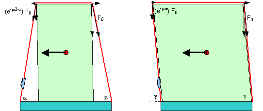
Figure 15: Transverse components of transverse tie-down lashings The transverse component of the tie-down lashing on the left in Figure 15 amounts to F0 × (1 – e–m×2×a) × cosa. The transverse component of the tie-down lashing on the right in Figure 15 amounts to F0 × (1 + e–m×p) × cos g. In order to clarify the orders of magnitude, an example with plausible values is obtained with: F0 = 2 kN, m = 0,25, a = 75°, g = 85°. Transverse component on left in Figure 15 = 0.25 kN; transverse component on right in Figure 15 = 0.13 kN. Neither value takes account of the possible elongation of the lashing belt by the change in geometric conditions. This entails more complex calculation, which is not shown here.
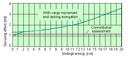
Figure 16: Securing effect in the transverse direction of a tie-down lashing with a = 80° Using a tie-down lashing with a = 80° by way of example, Figure 16 compares the securing effect according to a conventional assessment and the enhanced securing effect taking account of the transverse component and the increase in force due to a change in the geometry as a result of a sliding or racking movement. Up to a transverse movement of approx 1.9 cm, the effects differ depending on the direction of loading. In the event of loading towards the pre-tensioned side, smaller values are initially obtained. From 1.9 cm, the belt slips and the greatest possible transverse component, arising from Euler’s friction between belt and cargo, takes effect. In the event of loading on the opposite side, the belt slips from the start, so providing the greatest possible transverse component. It is thus clear that while the usual one-sided tensioning device does overall impair securing, so entirely justifying the k-factor, it does not bring about any detrimental asymmetry in the securing effect. The further increase is attributable to increasing elongation of the belt. Already with a transverse movement of 15 cm, the securing effect achieved in this example is a good twice that obtained in the conventional assessment. |
|
Top of page
| Contents
| |