
2 Conventional rules and calculation methods |
[German version] |
2.1 Direct lashingDirect securing connects the cargo and the vehicle with securing devices which are capable of transferring forces directly by tensile, compressive or shear stress. According to conventional assessment, this type of securing is limited solely by the strength capacity of these securing devices and the participating fastening points on cargo unit and vehicle. 2.1.1 Securing against slidingThe balances compare the load assumption related to the cargo mass with the friction plus the action of the securing devices. Friction is generally calculated using the coefficient of dynamic friction and the normal force = cargo weight. The action of the securing devices is made up of the horizontal force component plus the vertical force component multiplied by the coefficient of dynamic friction. In Source [1] , the balance for the transverse direction reads:
The balances in the longitudinal direction look similar. The balances are solved to find n or F in order to determine the necessary amount of securing. The stated approach is basically also used in the other sources. Sources [2] and [3] do not, however, specify force components with the assistance of the length components, but instead with corresponding angular functions of the lashing angles a and bx or by. The relations are::
Sources [2] and [3] additionally indicate a variant of the balance for securing against sliding with direct lashing and blocking, in which the blocking force BC is added to the securing forces without taking account of the stiffness of the blocking.
As to coefficients of friction, Source [3] makes use of "standard values" which are reduced by a factor of 0.85 in the sliding balance. These standard values are means from series of measurements of coefficients of static friction, which were multiplied by 0.925, and coefficients of dynamic friction, which were divided by 0.925, in each case for the same material pair. The balance in the transverse direction then reads:
2.1.2 Securing against tippingSecuring against tipping is only tested if the inherent stableness of a cargo unit is insufficient. The test criteria for inherent stableness are thus an integral part of the calculation model. According to Source [1], the test criteria for sufficient inherent stableness, where L, B, H = length, breadth, height of a (cubical) cargo unit with a center of gravity in the geometric center and fw = 0.2 (rolling factor) are: Testing of tipping stableness in transverse direction B : H > (fy + fw), Testing of tipping stableness in longitudinal direction L : H > fx The balance in the transverse direction reads:
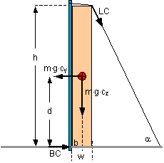
The balances in the longitudinal direction look similar, but without the rolling factor. The balances are solved to obtain n or F in order to determine the necessary amount of securing. The possibility of an asymmetric center of gravity is not addressed separately. Source [2] does not provide an adequate treatment of securing against tipping with the assistance of direct lashing. The test criteria for tipping stableness are as in [1], but with lack of clarity with regard to the coefficient of transverse acceleration to be used in the test. No separate tipping balance is stated, however, but instead a system of inequalities, which are intended to demonstrate both sliding and tipping resistance in the event of securing with diagonal lashing combined with blocking. The system of inequalities is, however, only appropriate for demonstrating securing against sliding, albeit while disregarding the different load generation of lashing and blocking (see 2.1.1). It is unusable for demonstrating securing against tipping and readily leads to erroneous results. In the original text, the formulae for the transverse direction with n = 2 lashings per side are: Formel 17: Formel 18: Formel 19: BC = blocking force [kN] a = vertical lashing angle b = horizontal lashing angle mD = coefficient of dynamic friction LC = lashing capacity (admissible lashing force) [kN] cy = coefficient of transverse acceleration cz = coefficient of vertical acceleration m = cargo mass [t] g = acceleration due to gravity [m/s2] The variables d, b, w and h are illustrated in Figure 11. Figure 11 shows a securing situation as presented in VDI Guideline 2700, Sheet 2, Figure 14.
Figure 11: Application of testing of securing against tipping to DIN EN 12195-1 Formula 17 corresponds to the conventional approach to demonstrating sliding resistance. Formula 18 is intended to demonstrate securing against tipping by lashing. Blocking makes no contribution to tipping resistance. Formula 19 is superfluous in this respect. An example calculation shows the unsuitability of formula 18 with the values m = 10 t, cy = 0,7, cz = 1, h = 3,0 m, d = 1,5 m, b = 0,25 m w = 0,5 m, a = 64°, by = 0°,mD = 0,4, n = 2
According to Source [1], the tipping balance reads:
The following replacements are made for comparability: H/2 = d, B/2 = b, H = h, B = w. Der Winkel a liefert die Größen Y, Z und L. Z = h = 3,0 m, L = h/sina = 3,34 m und Y = L × cosa = 1,46 m.
The formula according to source [2] provides a result in this example which is substantially too small. The difference becomes all the more serious, the greater is the coefficient of friction mD, which fundamentally has no place in a tipping balance. Source [3] contains a reduced rolling factor, the calculation being intended to be carried out with a coefficient of acceleration cy = 0.6 for cargo units at risk of tipping and direct lashing. Testing of tipping stableness is, however, calculated with cy = 0.5 and cz = 1: Testing of tipping stableness in transverse direction b : d > cy : cz, The recently included tipping balance is equivalent to the one stated in source [1]. The partially unsuitable system of inequalities, which is already to be found in source [2], is however additionally still present. |
|
Top of page
| Contents
| |