
1 Investigation of load assumptions |
[German version] |
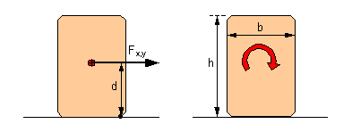
1.5 Rolling factorThe rolling factor was introduced by VDI Guideline 2700 and "takes account of dynamic tipping moments brought about by a non-steady-state lateral inclination or by angular acceleration from rolling oscillations of the vehicle about its longitudinal axis". This description is unambiguous and complete. It relates to dynamic tipping moments. The quasistatic tipping moment on a cargo unit is calculated from the force Fx or Fy acting at its center of gravity multiplied by the distance d of this force vector from the effective tipping axis (Figure 7 left). The force Fx or Fy is also the force which must be taken into account when securing the cargo against sliding. Dynamic tipping moments in the longitudinal or transverse directions arise from the rotational inertia of the cargo mass against the angular acceleration caused by pitching or rolling oscillations. These give rise to a "dynamic" turning moment on the cargo unit in question which is independent of the location of the tipping axis and center of gravity of the unit (Figure 7 right). The following applies to the magnitude of this additional moment: Transverse direction : For homogeneous or hollow cubical cargo units, the moment of rotational inertia J about an axis through the center of gravity may be approximately determined by:
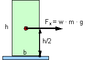
Figure 7: Static and dynamic tipping moment The applicable VDI Guideline 2700, Sheet 2 requires an allowance of 0.2 g for securing cargo units at risk of tipping on the assumption of sideways acceleration of 0.5 g. The rolling factor is explicitly not used for testing and dimensioning the securing against sliding of these cargo units at risk of tipping. In order to verify the reasonableness of the order of magnitude of this rolling factor, the rotational inertia of a cargo unit at risk of tipping (h ³ 2 × b) of maximum height (road transport: h = 3 m) is converted into an allowance w for transverse acceleration.
Figure 8: Conversion of a rotational tipping moment into a rolling factor Tipping moment from rotational inertia: Equivalent tipping moment: Acceleration allowance, homogeneous: Acceleration allowance, hollow:
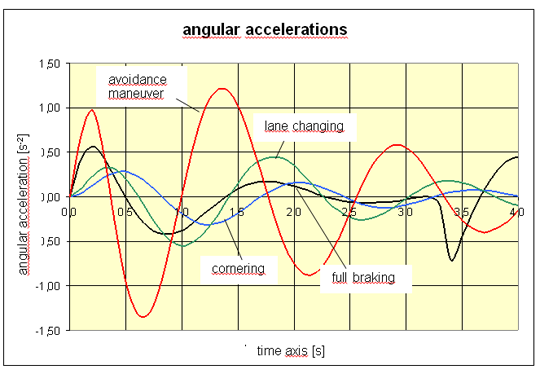
The angular acceleration from rolling oscillations or pitching oscillations to be used may be estimated from the described simulation calculations. Since these simulations may all be considered borderline situations, the results are usable for the stated purpose. Full braking, cornering and lane changing exhibit maximum angular acceleration values of 0.5 s-2 or lower (3). Only the avoidance maneuver exhibits distinctly larger values of up to 1.3 s-2. It must, however, be borne in mind that, due to phase shift, these elevated angular acceleration values without exception occur together with relatively small centrifugal forces, such that the effective transverse acceleration values still remain far below 0.5 g. This offsets the need for a larger rolling factor. If generous angular accelerations of up to 1 s-2 are used for the calculation, this justifies an acceleration allowance for securing against tipping of 0.064 to 0.115 g. In the vast majority of cases of full braking, cornering or lane changing maneuvers, however, half this value would be sufficient. A requirement still remains for real world measurements.
Figure 9: Angular acceleration values for pitching or rolling oscillations For securing unstable cargo units against tipping, the relatively recent draft of DIN EN 12195-1 (01/2009) only requires 0.6 g to be assumed as transverse acceleration, i.e. an allowance of 0.1 g. An equivalent pitching factor does not apply in the longitudinal direction of the vehicle. The conclusion which may be drawn from the above considerations is as follows: It is possible to support the assumption of 0.1 g as a reasonable acceleration allowance for securing cargo units at risk of tipping against tipping. The allowance should, however, also be used for securing such cargo units against tipping in the longitudinal direction. |


|
Top of page
| Contents
| |