
| Photo of the month – February 2021 |
[German version] |
| This month, we are again able to present two articles for you. |
|
 |
 |
| Pregnant truck | Out of the box!! |
Out of the box!!
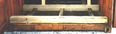
This month, we once again have the opportunity of bringing you a Photo of the Month from the maritime world. Thanks to our collaboration with the Cargo Incidents Notification System (CINS), we are able to serve up a very tasty failure of load securing.
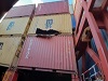
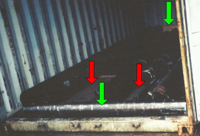
The yellow container is located in the second layer on the deck of a container vessel. The heavy steel members on the right of the photo are part of a lashing bridge. The term “lashing” has always been used at sea to refer to securing things, usually with ropes. The stacks of containers on deck were secured crosswise, so that each individual stack stands firmly like a tower and is independently secured. It is not intended that any of the towers lean against their neighbors. Steel lashing rods and turnbuckles are used to secure the stack.

We immediately notice the long hole in the side of the container.
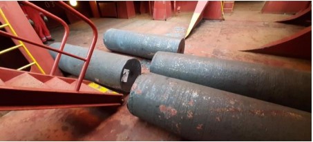
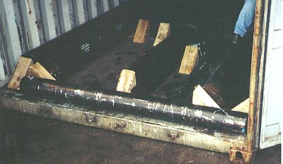
The mystery surrounding the hole in the container is soon cleared up. The container was loaded with solid steel rollers (round bars). The problem with cylindrical cargo is that it is able to roll and therefore offers no friction in a lateral direction – or at least none that can be usefully employed when securing the load. This means that the cargo has to be 100 % secured against lateral acceleration forces.
Each of these round bars weighs in at a good 5-7 tonnes. Because they are cylindrical, there was no longer any friction to prevent them from rolling back and forth with the movement of the ship after they had broken free of the load securing measures (which were clearly entirely inadequate). Because they were so heavy and were able to roll back and forth many times, the container, which appears to have been in a good condition, was unable to withstand the forces generated. And this was a hazard for the crew, the vessel itself and the rest of the cargo. We can only imagine what might have happened if a crew member had been using the companionway we can see in the photo or if the round bars had crashed into a container full of hazardous goods, or a refrigerated container full of vaccine.
But section 5.2.14.10 of the Container Handbook, “Round bars and profiles”, provides plenty of suggestions and options for stowing and securing cargo such as this properly.
Long round bars, profiles and similar cargoes, especially when carried in large weights, are ideally suited to transport on flatracks, providing that there is no risk of depreciation due to corrosion.It is generally straightforward to load, pack and secure such cargoes on flatracks, especially those equipped with stanchions. Loop lashings to the side and wooden bracing in the lengthwise direction are usually a quick and economic solution for virtually any long loads. Open-top containers provide better protection from weather and can also be packed straightforwardly, but have fewer cargo securing options than do flatracks.
It is only with difficulty and using special aids and working methods that the above-stated cargoes can be packed in standard box containers, with packing often being easier than the subsequent unpacking.
Packing can proceed relatively straightforwardly if special load suspension devices, such as specially designed C hooks, are available.
 |
|
Inserting a round bar into a box container using a C hook |
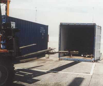
For various reasons, packing with conventional ground conveyors, such as forklift trucks with a low load-carrying capacity, is not very economic:
- Repeated forklift truck maneuvers are needed in order to position the cargo lengthwise in the container door area.
- The cargoes must be pushed into the container with the forklift truck, so dramatically increasing the risk of floor damage.
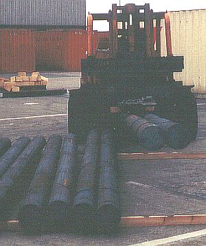
Cargo handling can be carried out more efficiently if it is possible to use forklift trucks with a very high load-carrying capacity (relative to the weight of the cargo), as, in the method shown, the load center distance is a very long way from the fork face.
 |
|
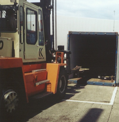
| Using a high capacity forklift truck |
The load-carrying capacity of the forklift trucks used must vastly exceed requirements, as the forks and lifting apparatus may be damaged by unevenly applied forces.
 |
|
| Wrong – the container floor can be scratched when pushing cargoes in and equipment may be damaged too. |
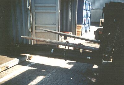
The chain used here with the forklift truck is too long. The forward end of the round bar is touching the floor. No further adjustment of the mast is possible. Lifting the forks is of only limited assistance, as not all forklift trucks have such a large free lift or such a low overall height that the cargo can be set down directly. In most cases, such cargoes will end up being pushed into place.
 |
|
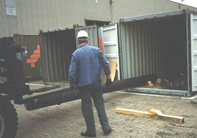
| Inserting a round bar with a forklift truck |
With two chains attached, the round bar can be steered better. Placing wedges once the roll has been set down to secure it provisionally and prevent it from rolling away is a useful accident prevention measure. They are not entirely suitable for cargo securing.
 |
|
| Risk of dangerous sagging |
It must be checked in every case whether the cargo can tolerate being handled as illustrated or whether it could be damaged in this way.
Warning: A forklift truck should only be used in this way if there is no risk of breaking accident prevention regulations or damaging the cargo.
 |
|
| Inserting profiles with a forklift truck |
 |
|
| Stowing without gaps or filling any gaps which occur is a fundamental requirement. Advantageous: Buffer stow in the door area |
It is certainly correct and important to protect the front end wall of the container with sufficiently strong and tall squared lumber members before round bars are pushed in or set down. If, as in the door area, a suitably sized round bar is available, it should be used as a buffer, but obviously only, as in the present case, with a single layer stow. Correct sizing of the wooden members or using cargo as a buffer precludes penetration through the front end wall and the doors.
 |
|
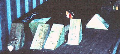
| Incorrect use of material: the wedges: |
It makes no sense to use costly wedges to "plug" gaps or as "wooden fixings". On the plus side, it should be noted that the wedges have been correctly cut for the use shown. Nailing into the face grain is possible. The only problem is, just what can two, three or four nails driven into a 1 inch container floor do to withstand such masses? Filling the gaps with squared lumber offcuts or beam format lumber (e.g. 6 cm x 8 cm) is entirely sufficient. Even roofing laths (e.g. 3 cm x 5 cm or 4 cm x 6 cm) would still be sufficient. Such wooden members need only be fitted into place and attached to the floor.
 |
|
| Incorrect use of wooden wedges |
Incorrect use of the wedges is even more obvious in this case and there are incorrectly cut wedges there too.
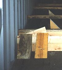 |
Inadequate result, despite the correctly cut wedges |
Although the wedges have been correctly cut, adequate securing force cannot be achieved with them. The nails driven into an approx. 1 inch container floor cannot provide sufficient cohesive resistance. However, the wedges are placed incorrectly by the round bars to provide a sideways securing action.
The following method may be used for a single layer stow:
| Wooden buffer member at the container front end wall |
 |
First of all a sufficiently thick and tall squared lumber member is fitted between the container front corner posts. If wooden members of an appropriate thickness and height are not available, the buffer is produced from several pieces of squared lumber. The wooden members should be at least half as tall as the round bars to be stowed.
 |
Round bar from the cargo as buffer |
Alternatively, if the batch to be stowed also includes shorter round bars, which can fit crosswise into the container, one of them can be used as a buffer. In this way, there is no need to use lumber to create the buffer.
| Round bars stowed against the front end wall buffer |
 |
The round bars are stowed against the front end wall buffer and tightly against the container side. For safety reasons, small wooden wedges should be laid beside each bar as it is put in place so that the bars remain in position.
 |
Gap between round bars filled with bracing |
| Wooden bracing to fill the gaps between the bars |
The precise distance between the bars and the height of the center point are determined. Two of the wooden braces shown are built outside the container from offcuts and a wooden member cut a few millimeters longer than to fit and are then fitted between the bars.
Only the squared lumber member at the central bar axis height must be correctly cut to size. Since the wooden members are a few millimeters too long, they have to be driven in crosswise and so provide a somewhat larger contact area. The other wooden members can be waste and offcuts.
| Enlargement of contact area |
 |
The strip-like bearing surface at (a) can be calculated to apply 100 daN per square centimeter of contact area. Hollowing out the ends with a chain saw (b) or cutting a slight bird’s mouth (c) can increase the bearing area and also improve the grip of the wooden members.
 |
|
| Placement of cross braces – plan view |
The bracing members should be placed in each case a quarter of the bar length from the ends of the bars.
If the calculated values for two cross braces are insufficient for the mass of the cargo, appropriately thicker wooden members or a larger number of cross braces should be used.
| Base beam for shoring |
Close to the bracing, the internal width of the container is measured within the corrugations. A 6 cm x 8 cm beam or an 8 cm x 8 cm squared lumber member is cut to exactly this length and then fitted into the container.
| Bracing and base member for shoring |  |
As an alternative to the four preceding operations, the following method may be used:
 |
|
| Combined wooden member for suspension from above |
A squared lumber member is cut exactly to the size of the gap. As described previously, a beam is cut to the internal width of the container between the corrugations and, using a few pieces of waste lumber, the bracing member is nailed centrally under the base member for the shoring so that it exactly fills the gap between the round bars:
 |
|
| "Combined member" in place |
The details stated above regarding the size of the contact areas and calculating the achievable strengths apply here too.
Two shoring members (a) are cut to size to rest on the base member and set in place in accordance with the following diagram so that they are braced against the top side rails. The wooden members are driven apart with a few hammer blows (b) and a securing member (c) is nailed in place to prevent the shoring members from moving back inwards.
 |
|
| Shoring for securing round bars |
It is not necessary to secure the shoring members against shifting in the lengthwise direction if they are fitted directly into the container corrugations at the top. With smooth container walls, however, "X-bracing" in the lengthwise direction would be essential.
The round bars are now fixed in the crosswise direction in such a way that they can withstand any movements which will occur in transit:
 |
 |
|
| Effectiveness of shoring at a tilt of 45° to the side | ||
Gaps in the door area must be filled with bracing to counter lengthwise movement. The method used is selected on the basis of the cargo mass, size of the gaps and similar factors.
 |
 |
 |
|
| Lengthwise bracing variants | |||
This Figure shows bracing for moderate cargo weights:
 |
The lengthwise wooden members are 10 cm x 10 cm in size. A total cross-sectional area of 300 cm² is thus available which bears perpendicularly to the grain of the 14 cm x 14 cm crosspieces. On the basis of a rough calculation, the bracing can withstand a lengthwise load of 300 cm² lumber cross-section x 30 daN/cm² of cross-sectional area = 9,000 daN. If the lengthwise members had also been 14 cm x 14 cm in size, loading capacity would have been almost doubled: 3 x 14 cm x 14 cm x 30 daN/cm = 17,640 daN.
We have explained technical terms from our Container Handbook in a Glossary. You will find it here.
Your Load Securing Team
Back to beginning