
2 Mathematical analysis |
[German version] |
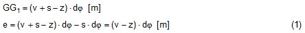
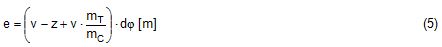
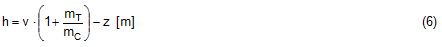
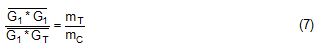
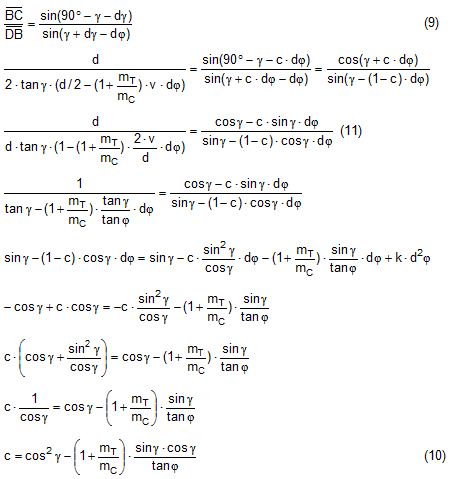
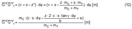
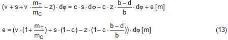
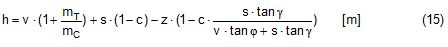
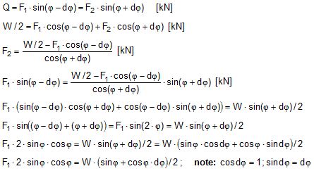
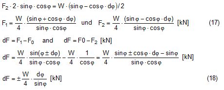
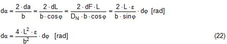
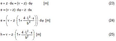
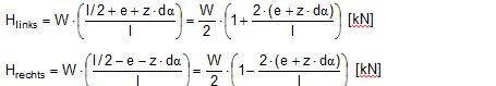
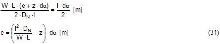
2.1 Vertical secondary suspensionFigure 2.1 shows a suspension arrangement with primary and secondary slings. The mass of the spreader is ignored. 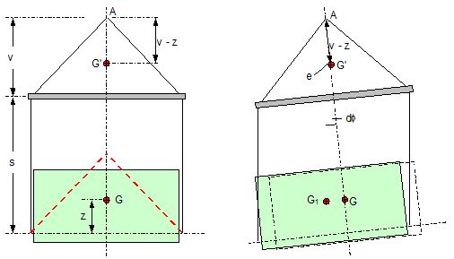 Figure 2.1: Virtual position of the c.o.g with ignored mass of spreader In the left part of Figure 2.1 the cargo unit hangs straight. In the right part it is tilted by the small angle df caused by an initially unknown eccentricity e of the centre of gravity. This eccentricity shall be determined as the difference between the total shift of the centre of gravity GG1 and the slewing of the cargo unit s × df, caused by the secondary suspension. Die Distanz (v – z) unterhalb des Aufhängezentrums führt zu einem Punkt, an dem die Ausmittigkeite allein die Neigung df und die neue Gleichgewichtslage verursachen würde. Dieser Punkt ist der „virtuelle“ Schwerpunkt der aufgehängten Ladung. Die wirksame metazentrische Höhe der Aufhängung ist: This leads to the well-known practical rule: „Draw the primary suspension down to the base level of the secondary suspension. As long as the real centre of gravity is within the shifted triangle of the primary suspension, the cargo hangs stable:“ The above practical rule is not quite correct as it ignores the stabilising influence of the spreader. This influence is investigated below where the common centre of gravity G* of both the cargo unit and the spreader is considered. It should be noted that the influence of the mass of the spreader appears in the results below as a relation in the form of mT / mC. In case of a symmetrical suspension on both ends of the cargo unit, mT is the mass of both spreaders and mC is the full mass of the cargo unit. In case of asymmetric arrangements, where both ends of the cargo unit will be considered separately, mT is the mass of the considered spreader and mC is the partial mass carried by the considered arrangement. 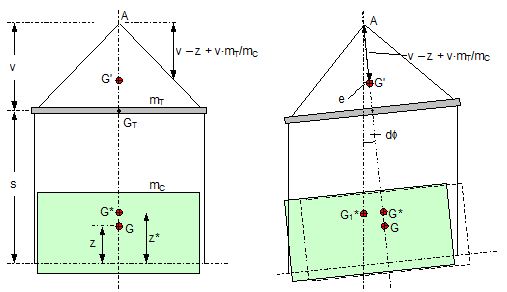 Figure 2.2: Virtual position of the c.o.g. with consideration of the mass of the spreader The level z* of the common centre of gravity G* of the cargo unit and the spreader is determined by: The common centre G* moves in the tilted condition to G1*. The distance of this movement is: This distance is also the unknown eccentricity e of the centre of gravity G plus the slewing distance s × df from the secondary suspension. The eccentricity e may be determined by equalisation with: The solution is: The virtual centre of gravity is lower by the amount of v × mT/mC than without considering the spreader mass. The effective „metacentric height“ of the suspension is: 2.2 Inclined secondary suspensionIn the previous considerations the secondary slings hang vertically and parallel. Consequently the tilting angle of the whole arrangement is always equal to the tilting angle of the secondary slings, namely df. With an inclined secondary suspension the slewing angles dg of the secondary suspension are different from dg and cause an additional tilting of the cargo unit. This will additionally influence the level of the virtual centre of gravity in either way, up or down, depending on the sign of g. 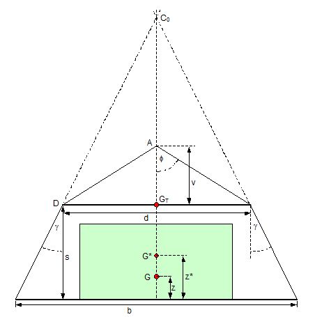 Figure 2.3: Arrangement with a positive angle g of the secondary suspension Figure 2.3 shows an arrangement with non-vertical secondary suspension at a positive angle g with the centre of suspension at point A and the common centre of gravity of spreader and cargo unit at point G*. The point C0 is the imaginary centre of the secondary suspension. With an unknown offset e of the centre of gravity the arrangement is tilted about the point A by the small angle df (see Figure 2.4). The common centre of gravity G*1 settles necessarily below the centre of suspension A. The cargo centre of gravity G1 is in line with G*1 and GT at a distance which reflects the inverse proportionality as follows: The imaginary centre of the secondary suspension C is vertically above G1 forming the triangle BCD (shaded light blue). The secondary suspension has consequently tilted by the angle dg. The magnitude of dg may be related to the magnitude df by the relation: The triangle BCD contains both the angles dg and df and is used for the determination of the factor c by means of the rule of sine’s. distance DB = d/2 – (1 + mT/mC) × v × df 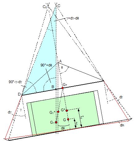 Figure 2.4: Arrangement tilted by df due to an offset of G Rule of sine’s: This solution shows that c depends from g and also from f. 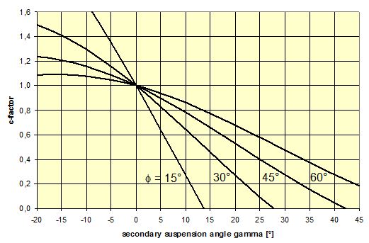 Figure 2.5: Factor c for mT/mC = 0.1 and f = 15°, 30°, 45°, 60°e The slewing of the secondary suspension causes a horizontal shift of the cargo unit and also an additional tilting. This is shown by the red lines in Figure 2.4. 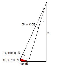 Figure 2.6: Shifting and tilting due to slewing of the secondary suspension The tilting about the angle dg causes a shifting of the cargo unit by the distance (s × c × df) to the left. This is associated with a lifting of the left side by (s×tang×c×df) and a lowering of the right side by the same distance. This causes the cargo unit to tilt by the angle da to the right. This applies for a positive angle g, when the offset e is directed to the left. If the centre of gravity G is positioned by the distance z above the slinging level, it will also be moved to the right by the distance z × da. The angle df is found by: The position of the virtual centre of gravity is determined by means of the still unknown eccentricity e as follows: The effective „metacentric height“ of the suspension arrangement is: This formula may be converted by means of the relations d = 2×v×tanf and b = d + 2×s×tang: 2.3 Flexible primary suspensionsThe previous analyses were taken under the assumption that the length of slings under load is always stationary, i.e. their primary elongation will not change due to small changes in the load when the hanging cargo unit is tilted. This is certainly justified with wire rope slings, which have an elongation that is governed by a modulus of elasticity of around 104 kN/cm2. However, the elastic elongation of long polyester slings is much greater and the secondary effect of changes in elongation due to tilting of the cargo unit may contribute to an additional loss of suspension stability. Figure 2.7 shows a dual crane lift with two identical primary suspensions using wire rope grommets. This is not critical in general. It might, however, become critical, if the wire rope grommets were replaced by polyester grommets. The following analysis is directed to the primary suspension of a cargo unit with the fixing points of the slings below the centre of gravity G. The slings have a distinguished elasticity so that the originally identical length becomes unequal under the influence of unequal loads. The analysis is carried out for the longitudinal view and for the transverse view. As the essential interest of the analysis is directed to parameters influencing the stability of the suspension, it is assumed that the arrangement is symmetrical in both the longitudinal and the transverse view. The forces in the slings are therefore identical in the initial condition. 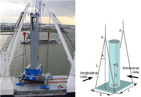 Figure 2.7: Dual crane lift with primary suspension, schematic presentation Longitudinal view The originally straight suspension is tilted by a small angle df caused by an initially unknown eccentricity e of the cargo centre of gravity. Due to the change of load in the slings the base b of the cargo unit is additionally tilted by the angle da. 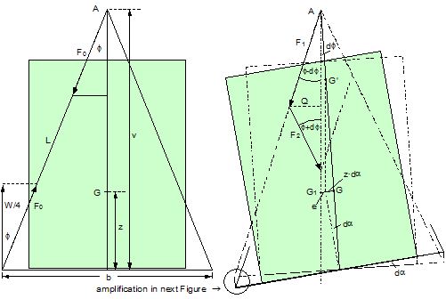 Figure 2.8: Primary suspension with elastic elongation differences in slings This additional inclination creates an additional shift of the centre of gravity, if it is situated above (or below) the slinging base b. The effect of this additional shift is already contained in the observed tilting angle df. In the upright condition (Figure 2.8 left) the force in each sling is determined by the total weight W = m × g of the cargo unit under the assumption of 4 symmetrical slings: The determination of the forces F1 and F2 in the tilted condition shall identify the relation of the force difference dF to the tilting angle df. Similarly: The force difference dF causes a change of length dL in the slings. This change of length may be conveniently determined by the nominal spring constant DN of the slings. The nominal spring constant DN of a lifting sling may be determined by: Test runs with polyester grommets have shown an e = 0.023 for DF = WLL. Allowing the load of WLL for a lifting operation, the applicable DN is obtained by: Due to the change in length dL the base of the cargo unit is tilted by the angle da. 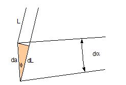 Figure 2.9: Tilting angle da due to elongation changes of slings The secondary transverse movement of the centre of gravity due to tilting by the angle da is equal to z × da with z = elevation of G above the slinging base b. The observed total tilting angle df permits to find the initially unknown offset e and finally the metacentric height, which allows the judgement of the suspension stability. The metacentric height h is reduced with growing values of L and de and with decreasing values of b. Transverse view There is no defined common centre of suspension in the transverse view. An initially unknown eccentricity e of the cargo centre of gravity causes a change of loads in the suspensions, namely an increase on the left side and a decrease on the right side in Figure 2.10. The slings react with elongation on the left side and shortening on the right side. This creates a tilting of the base of the cargo unit which amplifies the transverse movement e of the centre of gravity by the distance z × da. The total distance (e + z × da) is finally responsible for the change of loads. In the upright condition the forces in all slings are determined by the weight W = m × g of the cargo unit: In the tilted condition the forces in the lifting tackles H are: 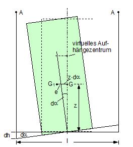 Figure 2.10: Dual crane lift in transverse view The forces in the slings are: The force differences are: The elongations in the slings are: The vertical components of these elongations are: The distance dh can be expressed also by: This permits to determine the initially unknown offset e: With the nominal spring constant defined above the metacentric height is: The metacentric height h is reduced with growing values of v and e and with decreasing values of l. 2.4 Asymmetric arrangementsThe analyses in the previous chapters were directed to arrangements with identical configurations of slings and spreaders on both ends of the cargo unit. However, there are quite often arrangements with different configurations on both ends, having e.g.:
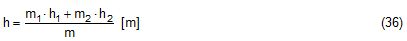
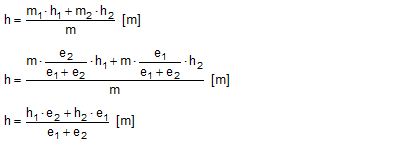
Figure 2.11 shows an asymmetric suspension with a single primary sling fixed below the cargo centre of gravity on the left side and a combined primary/secondary suspension fixed above the centre of gravity on the right side. The arrangement is obviously stable, but the safety margin is unknown.  Figure 2.11: Asymmetric suspension Figure 2.12 shows the principles of the asymmetric suspension in Figure 2.11. 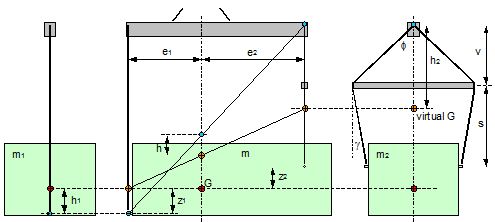 Figure 2.12: Asymmetric suspension The left side carries the partial mass m1 and the right side the partial mass m2. The partitioning follows the rule of inverse proportionality: Left side: The single primary sling will be definitely vertical in the transverse plane. If fixed to the cargo unit below its centre of gravity, it will create an instable suspension with the negative metacentric height h1. If the cargo unit is tilted by the small angle df, a negative stabilising moment will be produced. Right side: The suspension with a spreader will cause the effect discussed in chapter 2.2. The centre of gravity of the partial mass m2 is raised to a virtual position with a still positive metacentric height h2. If the cargo unit is tilted by the small angle df, a positive stabilising moment will be produced. The algebraic sum of both moments is equal to the moment of the total mass m with the lever coming from the common metacentric height h. The sign of the common metacentric height h decides on the stability of the whole suspension. Figure 2.12 contains also a geometrical approach for obtaining the common metacentric height h. In the side view the two individual centres of suspension (blue points) are connected by a straight line and the two active centres of gravity (orange points) are connected by a straight line. These lines intersect with the vertical line through the common centre of gravity and indicate the common centre of suspension and the common virtual centre of gravity. The vertical distance between these points is the common metacentric height h. It is positive in this example. The suspension is stable. The proof of the correctness of the geometrical solution is shown as follows: The last equation shows h as the weighted mean of h1 and h2 in the geometrical solution. |


|
Top of page
| Contents
| |
||