
3 Miscellaneous |
[German version] |
3.1 Rolling factor3.1.1 Physical causesThe „rolling factor“ is one of the contentious issues surrounding the securing of cargo on road vehicles in Europe. This value used in calculation first makes a one-off appearance in the German VDI 2702 Guideline and then subsequently in the EN 12185-1:2003 standard as a supplement to the lateral acceleration factor 0.5. In both cases, this supplement has a magnitude of 0.2 and is only to be used for assessing securing against tipping in a lateral direction relative to the direction of travel if the cargo unit concerned is not innately stable given a lateral acceleration of 0.7 g. The reason given for this supplementary factor is to „take account of dynamic tilting moments brought about by a non-steady-state lateral inclination or by angular acceleration from rolling oscillations of the vehicle about its longitudinal axis when the vehicle is cornering“. The report „Securing cargo in road transport – Who knows the truth?“ demonstrated that when steady-state cornering is initiated rapidly, when changing lanes and in the event of rapid avoiding action, the increase in lateral acceleration is overlaid by angular accelerations from oscillations of the loading surface about the longitudinal axis of the vehicle. Depending on the suspension of the vehicle, such oscillations can occur with a periodicity of around 1.5 s and amplitudes of around 3°. The angular accelerations from these oscillations are of the magnitude 1 s-2 and bring about tangential forces. Together with centrifugal force and the parallel component of the force of gravity due to the inclined loading surface, these are included in the calculation as the common inertial force in the centre of gravity of the cargo unit. This means that the tangential forces from the angular accelerations are integral components of the lateral force resulting from the specified lateral acceleration of 0.5 g. The quasi-static tilting moment of the cargo unit is made up of this lateral force and the vertical lever between the centre of gravity of the cargo and the tipping axis. In this common and perfectly usable conceptual model, it is, as a simplification, assumed that the mass of the cargo unit is concentrated at its centre of gravity. In fact, however, any mass has a spatial dimension and reacts to angular accelerations with rotational inertia. This rotational inertia in turn leads to an additional tilting moment, which is not included in the mathematical model used, because a punctiform mass cannot possess rotational inertia. The somewhat complex calculation of this additional tilting moment is replaced by a fixed increase in the assumed lateral acceleration in the guidelines and standards referred to. This is the background to the justification for the rolling factor cited above. The report „Securing cargo in road transport – Who knows the truth?“ used plausible assumptions to calculate that this rolling factor should have a maximum of 0.1 g, due to the mechanisms described. In fact, even this value can only be achieved with a cargo unit whose height and width are at the limit of what is permitted on the roads, i.e. a cargo unit that possesses a considerable amount of rotational inertia. It is unclear why those who introduced the rolling factor opted for the rather large value of 0.2 g. Records or minutes of the consultations do not exist or are not available. One supposition is that the suspension of commercial vehicles in the past was rather different and the damping properties of such systems were not as good as in modern-day commercial vehicles, with the result that far larger rolling oscillations were used in the calculations. It is also possible that a larger rolling factor than would have been required by the additional tilting moment due to rotational inertia was intended to limit the tilting of cargo units as described in several places above and the associated dynamic effects. Top of page 3.1.2 Problems with acceptanceWhereas this rolling factor was defined with a value of 0.2 g in DIN EN 12195-1:2004, it was reduced to 0.1 g in DIN EN 12195-1:2011 on the basis of additional, independent expert opinions. However, the standard made the use of the rolling factor subject to conditions which effectively „abolished“ it. For the coefficient of lateral acceleration cy, these conditions are as follows:
The majority of cargo-securing scenarios on the roads are tie-down lashings, of which only a small proportion are intended to secure the cargo against tipping. In virtually all such cases, the pre-tensioning force that can be achieved is likely to be equal to STF, with the result that a value of 0.5 for cy can be used for calculation, i.e. the rolling factor need not be used. We should not forget to mention that in the same standard the criterion for establishing tipping stability has been formulated incorrectly. There, proof of tipping stability is given as:
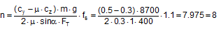
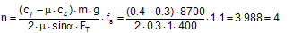
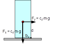 Figure 41: Tipping stability as a result of inherent stability The following should be used: cy = 0.5 and cz = 1. In this case, according to the standard, a cargo unit where, for example, by = 0.55×d would still not be at risk of tipping. According to the standard, it would be possible to secure this cargo unit using only blocking methods at its base to prevent it from sliding. In fact, however, the rotational inertia of a body is always present. It does not only appear if the cargo is liable to tip, as the note on the use of the rolling factor could possibly suggest. Consequently, it is necessary to check the inherent stability with a fixed tilting moment of 0.6×m×g×d. However, with a stability lever of b = 0.55×d, the inherent stability moment is only 0.55×m×g×d. This would therefore not be able to prevent tipping alone. The checking criterion should therefore be changed accordingly. Similar oscillations of the loading surface about the lateral axis also arise as a result of a rapid braking manoeuvre or aggressive pulling away. Such oscillations are known as pitching oscillations. Their amplitudes are smaller than those of rolling oscillations. On the other hand, their periodicity is shorter, so that the possibility of angular accelerations of the same magnitude as with rolling oscillations cannot be excluded. However, there are no known studies of this and none of the current German guidelines or standards make use of a „pitching factor“. Because the rolling factor was unknown in the rest of Europe and elsewhere in the world, its inclusion in the EN 12195-1 standard in 2003 was criticized by a good number of the delegations, in particular the Swedish delegation. As part of the practical trials in Sweden in 2004 already mentioned in Section 1.5.2, investigations were therefore carried out to identify whether the rolling factor was justified. However, the trials with a fully-laden truck were not fit for purpose as cargo units with relatively small dimensions were used as test objects (stacks each containing two rolls of paper with a total height of 2.27 m and a diameter of 1.0 m). The test also did not explicitly look at the effect of rotational inertia coupled with angular accelerations. The cornering manoeuvres were initiated extremely carefully and the maximum lateral acceleration was only reached after approximately 15 seconds, so that overlaid rolling oscillations were not able to develop. Instead, tie-down lashings with different pre-tensioning forces were tested, which delivered results that were able to confirm the additional securing effects of tie-down lashings and to disprove a number of assumptions made in the EN 12195-1:2003 standard, which had just been published. The findings of the corresponding trials that are marginally relevant with respect to the rolling factor were that the vehicle’s additional support wheel made contact with the ground at measured lateral accelerations significantly below 0.5 g. This led to the conclusion that the universally accepted assumption of a lateral acceleration of 0.5 g provided a considerable safety margin with respect to cargo securing, as this value would extremely rarely be achieved in practice. It is more likely that the vehicle would overturn. In 2011, the CEFIC position paper already mentioned in section 1.3.4 on the EN 12195-1:2010 standard surprisingly included a statement on the rolling factor and its actual origin as a compensatory factor for the moment of rotational inertia. In the same breath, however, it rejects the idea of angular accelerations of sufficient magnitude during normal operation of a commercial vehicle that occur concurrently with other lateral accelerations that would justify the use of a rolling factor. However, CEFIC fails to provide any reference to plausibility considerations, calculations or measurements. This uncertainty regarding how to handle the undeniable presence of rotational inertia of cargo units continues to this day. The draft of a new version of the German VDI 2700, Part 2 Guideline includes the rolling factor as a stability coefficient with a value of 0.1 g, as does the DIN EN 12195-1:2011 standard, but not only in the context of securing against tipping to the side, but also against tipping to the rear, although not to the front. The limitations included in DIN EN 12195-1:2011 are not present. This means that this factor is therefore intended to be used with both direct lashings and tie-down lashings. In the international consultations regarding a new version of the Guidelines for Packing of Cargo Transport Units in the form of a new code(10), the rolling factor was rejected, partly on the evidence of the results of the Swedish trials and the actual or supposed safety margin resulting from the assumption of 0.5 g lateral acceleration. The „German rolling factor“, whatever deep significance it might have, would be covered by this safety margin. This supposed or actual safety margin gives rise to economic considerations. If the lateral acceleration that can be achieved under normal operating conditions on the roads really were smaller by the margin claimed here, the majority of all cargoes that are not liable to tip and are lashed down correctly with tie-down lashings would be „over-secured“ by some 50% to 100%. This is the consequence of the considerable non-linearity of the ratio between the coefficient of friction and the number of tie-down lashings required as described in Section 1.2. We shall demonstrate this with a brief example. Example: A cargo with an overall weight of 8700 daN is secured against sliding laterally with tie-down lashings using belts. Coefficient of friction μ = 0.3. Pre-tensioning force FT = 400 daN, lashing angle α = 90°. According to DIN EN 12195-1:2011, the number of belts required is:
If we had assumed a lateral acceleration of 0.4 g, i.e. without the safety margin that is being claimed, half the number of belts would be required in the same situation. This means that the „unnecessary“ effort expended on securing the cargo would have been 100%.
This consideration should encourage us to identify more reliable acceleration assumptions and make these available in the long-term. Values such as these should also be made dependent on the vehicle type, its suspension and other relevant characteristics. Until such time as this is done, the value of 0.5 g will remain unchanged, even for securing scenarios involving only sliding. The additional risks for non-stable units resulting from their rotational inertia should be mitigated by additional securing measures in the interest of all parties involved, without being required to do so by a standard or a code. This is even more important the higher and wider a cargo unit is, i.e. the greater its rotational inertia. Top of page 3.2 Tipping testAnnex D of the DIN EN 12195-1:2011 standard contains a description of the „Practical tests for determination of the efficiency of cargo securing arrangements“. These tests can be performed as an alternative to the suggested calculations and are particularly useful for cargo securing arrangements of a complexity that precludes simple, deterministic calculation. Typical applications include securing cargoes on pallets using shrink film and the use of plastic nets for securing. There are two methods to choose from: Dynamic driving tests in accordance with EN 12642:2006 or an inclination test(11) described in greater detail in Annex D of DIN EN 12195-1:2011. In the national preface to DIN EN 12195-1:2011, the complaint is made that the static tipping test (= inclination test) does not include dynamic effects. This criticism is intended to point out that securing arrangements that would pass the static tipping test may fail in a dynamic driving test. The static tipping test is also subject to the criticism that it uses the „mean“ coefficient of friction μ for tie-down lashings and blocking instead of the explicit coefficient of dynamic friction μD as was used in the 2004 predecessor to the standard. 3.2.1 Equivalence to mathematical modelsBoth these types of practical tests should be in a position to replace mathematical testing using the simplified mathematical model, and should therefore be equivalent not only to this model, but also to each other. Even at first glance, and without the need for extensive, long-term testing, it is clear that such equivalence can hardly be expected. We shall below make some remarks that are not intended to provide answers to open questions, but rather to attempt to state such questions more precisely. Once again, tie-down lashings are the focus of our attention. The simplified mathematical model laid down in DIN EN 12195-1:2011 assumes a stationary horizontal acceleration and leaves the gravitational effect unchanged at 1 g for transportation on the road. The securing effect of the tie-down lashing is restricted to the increase in friction resulting from the vertical components of the pre-tensioning forces STF on both sides, with these being reduced by a safety factor. The mean value μ is used as the coefficient of friction. In terms of the stationary vertical and horizontal accelerations, the static tipping test is identical with the simplified mathematical model. However, this assumes that the mean coefficient of friction used to determine the test inclination is the same as the actual coefficient of static friction. By definition, however, this is not so, because the mean coefficient of friction used is only 0.925 times the coefficient of static friction. This discrepancy means that the test inclination is set to a larger value than would be necessary with the actual coefficient of static friction. This means that the static tipping test gains a small safety margin. However, in the majority of cases this safety margin is exhausted and even exceeded because the greater amount of friction that actually applies makes the test appear to be successful with a smaller securing effect than the mathematical model requires with the smaller amount of friction. According to DIN EN 12195-1:2011, the tipping test is judged to be successful if the cargo unit under investigation „remains in position and only moves to a limited degree“ at the test inclination. Let us take an example to illuminate this rather opaque situation. The securing effect SE of a tie-down lashing or similar securing arrangement required by the mathematical model results from the difference between the inertial force and the friction from the weight at the mean coefficient of friction μ used for calculation. Let us assume that the actual coefficient of static friction in this example is μS = 0.4. The resulting mean coefficient of friction is μ = 0.925 × 0.4 = 0.37. Let the weight of the cargo be 1000 daN. We are looking for the securing effect against sliding to the front under breaking deceleration of 0.8 g. Mathematically necessary securing effect: SE = (0.8 – 0.37) × 1000 = 430 daN At μ = 0.37 we get an angle φ = 44.1° for the tipping test. The test is successful and the cargo does not slide. However, because the actual coefficient of friction of 0.4 is acting, rather than the mean coefficient of friction μ = 0.37, a smaller securing effect than that calculated is sufficient. Securing effect that is sufficient in the test:: SE = (0.8 – 0.40) × 1000 = 400 daN This means that the tipping test requires less securing effect than the mathematical model. This weakness of the tipping test is mitigated somewhat by the fact that it represents the securing effect a little closer to reality, i.e. it takes account of small, permitted movements and deformations of the cargo, which can include a temporary drop in the coefficient of friction towards the value of the coefficient of dynamic friction. On the other hand, the dynamic effects that occur during a real emergency braking manoeuvre are not accounted for. These primarily take the form of fluctuations in the apparent weight due to vertical accelerations. Dynamic driving tests rarely accurately reflect the mathematical model. The horizontal acceleration can be greater or smaller than the test value and includes overlaid fluctuations. Fluctuations in the vertical force lead to fluctuations in the friction. But here also the actual coefficient of static friction applies, which is higher than the mean coefficient of friction required by the mathematical model. On the other hand, a trend has been observed towards more pronounced movement of the cargo and hence a lower coefficient of dynamic friction. The securing effect of the tie-down lashing is rendered absolutely realistically. From a realistic perspective, we should, of course, expect that the mathematical model reflects the dynamic driving tests and not vice versa. But questions related to the representation of complex events using simplified mathematical models do not merely involve technical and physical issues. Instead, they have to be answered in the light of an economically justifiable level of risk acceptance. Top of page 3.2.2 PracticabilityIf we assess the criticized tipping test irrespective of its equivalents to the mathematical model laid down in the standard, we find that it is thoroughly practicable. Using suitable experimental equipment (e.g. a tipper truck), the inclination test as described in B.1.2 of DIN EN 12195-1:2011 is first carried out with the unsecured cargo and the coefficient of friction is determined with μ = 0.925 × tanα. On the basis of this coefficient of friction μ and the coefficients of acceleration cx,y and cz that apply to transportation, the angle of inclination φ for the actual inclination test is calculated. The cargo is then secured and subjected to this inclination φ using the same test equipment to determine whether the cargo remains in position. If the cargo does not slide, the securing effect is clearly sufficient. If it does slide, the test must be repeated after improving the securing. If suitable precautionary measures are taken, this inclination test can be repeated multiple times without the risk of damage to the cargo. Any improvements that need to be made with regard to securing can also be easily identified with no risk by observing the behaviour of the cargo during the test. This can hardly be done with a driving test. Top of page 3.2.3 Enhancement for any vertical accelerationsAnnex D of the DIN EN 12195-1:2011 standard has a further minor shortcoming. The scope of application of the standard includes transportation by sea and by rail. In these cases, the coefficient of acceleration cz can be less than 1. Table D.1 and Figure D.3, however, only provide the test angles φ for the vertical coefficient of acceleration cz = 1, i.e. only for transportation by road. The equation below provides the value for sinφ as a function of cx,y, cz and ϒ for all modes of transportation covered. The parameter ϒ stands for the coefficient of friction to be used or for the ratio between the resting moment lever and the tipping moment lever if the test is intended to demonstrate the stability of the cargo in respect of tipping.
A substitution is made in order to solve Equation (66) with a greater degree of calculational reliability. This is as follows:
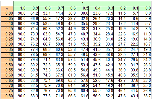
The value of r must be calculated and then used in the following, simpler equation:
The solution of Equation (67) can be verified against a table. The table shows the angle φ for the input parameters r and ϒ.
|


|
Top of page
| Contents
| |