
1 Tie-down lashing |
[German version] |
1.1 Essentials of tie-down lashingAs a way of securing cargo, the tie-down lashing is undoubtedly archaic, as cargo such as bales, barrels, jars and perhaps wooden crates that used to be transported on horse-drawn carts hardly lend themselves to being secured directly. This towering load of hay being transported on a wagon (Figure 1) provides an impressive demonstration of the tie-down lashing technique. The pole lying along the length of the hay is held down by two diagonal chains at each end. In addition, there are at least three ropes used as tie-down lashings across the load of hay. If we take a closer look, this arrangement of securing equipment covers virtually all the crucial aspects needed for a good tie-down lashing:
 Figure 1: Hay wagon with the load secured by tie-down lashings, © http:// kleinsthof.de There are many aspects to the securing effect of a tie-down lashing applied at right angles to the vehicle axis. The effect can be broken down into the following elements:
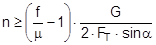
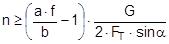
The complex mechanisms that govern the way in which these forces act mean that they cannot be represented with simple mathematical formulae. Indeed, they cry out for a simplified mathematical model to be developed that nevertheless encompasses the totality of all the effects. In the past, this has clearly only been achieved to a limited and insufficient extent. Top of page 1.2 Traditional assessment modelsThe traditional assessment model for tie-down lashings as described, for instance in the German VDI 2702 Guideline issued in May 1990 only makes use of the effects described in points 1. and 4. in the previous section. Thus, only the increase in friction resulting from the sum of the vertical components of the lashing forces is taken into account as having an effect to secure the cargo against sliding. In the same way, the securing effect against tipping is taken to be the sum of the vertical components of the lashing forces that increase stability. Expressed mathematically, the balances are as follows:
f = coefficient of acceleration (0.8 to the front, 0.5 to the rear and to the sides) G = weight of the cargo to be secured [daN] μ = coefficient of friction between the cargo and the loading surface n = number of tie-down lashings FT = pre-tensioning force in the tie-down lashing [daN] α = vertical lashing angle [°] a = lever of tilting moment [m] b = lever of stability moment [m]
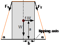 Figure 2: Traditional assessment of a tie-down lashing These two models have two invaluable advantages. They are equally applicable to the longitudinal and transverse directions with respect to the vehicle and they do not rely on evaluating the effects of small movements of the cargo. The securing effects derived from small movements in the cargo, which taken together are considerably smaller than the primary effect of increasing friction, are not taken into account. Of course, one could take the view that the cargo should not move anyway. This would, however, be inconsistent, because the traditional mathematical models for assessing direct securing arrangements imply a significant amount of cargo movement in order to exploit the full lashing capacity LC of the securing equipment (see Chapter 2). Furthermore, trying to compensate for a disequilibrium of forces or moments without any movement of the mass involved would contradict the laws of mechanics. Cargo that has been secured with tie-down lashings is permitted to move when subjected to an external load and, as shown in all trials, it duly does so. The mathematical models described above, which have certainly proved themselves in practice, have created the general impression among many practitioners that they provide a complete physical description of the securing effect of a tie-down lashing. This has led to the dogma that a tie-down lashing should be as close as possible to vertical, because the sine of the lashing angle a only achieves its maximum value at 90°. Also, one occasionally hears the argument that since the cargo does not move, it is only logical to use the coefficient of static friction for ì. These conclusions are not tenable, as we shall demonstrate in Section 1.4.It is, however, clear that the mathematical models above fail to take account of a considerable percentage of the potential securing effect of a tie-down lashing. To use these models therefore means to err on the side of caution, particularly if the lower coefficient of sliding friction is used for calculation. It is not known whether this mathematical safety margin was intended to compensate for any loss of pre-tensioning force as a result of the equipment being tensioned on one side only or the loss of tension in the tie-down lashings during a long journey or any uncertainty in assessing the level of friction. Unfortunately, we have no way of knowing what was in the minds of those who drew up these mathematical models. We must draw attention to a small, hidden shortcoming of the mathematical models described above. This relates to the dominant influence of the coefficient of friction μ or the resting moment arm b. If we consider the securing effect of the tie-down lashing separately in each of the models, the values ì and b have a linear impact, i.e. the securing effect is doubled if ì or b is doubled. Auf einen kleinen, verborgenen Makel der oben genannten Rechenmodelle muss noch hingewiesen werden. Es handelt sich um den dominanten Einfluss des Reibbeiwerts μ bzw. des Standhebels b. Betrachtet man die Sicherungswirkungen der Niederzurrung in beiden Modellen isoliert, so haben die genannten Größen μ und b einen linearen Einfluss, d.h. die Sicherungswirkung verdoppelt sich, wenn μ bzw. b verdoppelt wird.
This matches the intuitive expectation of any practitioner. However, if the complete balances are taken into account and used to determine the total number of tie-down lashings or the total pre-tensioning force required, this results in a markedly non-linear influence of the values μ and b. The examples below determine the number of tie-down lashings n required against the coefficient of friction ì and the resting moment arm b. In order to achieve this, the balance calculations above are solved for n.
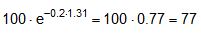
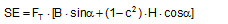
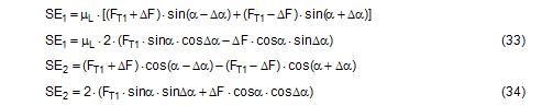
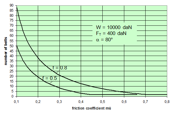 Figure 3: Influence of the coefficient of friction on the number of tie-down lashings required We can see that the relationship between n and μ or between n and b is hyperbolic rather than linear. The reason for this is that both μ and b not only influence the securing effect directly and linearly, but also play a considerable role in determining the securing effects needed from the tie-down lashing on the basis of the weight of the cargo. In terms of the underlying physics, this is correct, but it is incomplete because it ignores the other securing effects that essentially have the same nature as direct securing. This means that in the event of a low coefficient of friction μ, for example, the model would require a number of tie-down lashings that practitioners would intuitively feel to be excessive. This can, in turn, have an impact on the credibility of the simplified mathematical models among practitioners. If tie-down lashings are used, steps should always be taken to ensure a good coefficient of friction μ of at least 0.3. If this is done, the non-linearity of the relationship to the number of tie-down lashings is kept to a reasonable level. Furthermore, extremely small resting moment arms b are rare, so that the underlying distortion in the mathematical models as described is of little practical significance. Overall, we can therefore say that these models as used in the VDI 2702 Guideline of 1990, coupled with the recommendation that the coefficient of dynamic friction should be used, were both thoroughly appropriate and successful. The same applies to the slightly reworked version with the designation VDI 2700, Part 2, issued in November 2002. Top of page 1.3 Attempted improvements in EN 12195-1:2003During the consultation process for establishing a European standard to harmonize cargo securing around the turn of the millennium, a note that appeared in the VDI 2700 Guideline, Part 2 of November 2002, and which dealt with the issue of tensioners being arranged on one side only was taken up. This note indicated that if tie-down lashings are used and tensioners are only employed on one side, it may be appropriate to apply a greater pre-tensioning force on the side on which the lashing is tensioned, taking into account the permitted lashing force and the difference in pre-tensioning force that initially arises as a result of the losses due to the belt passing over the cargo. The note appeared in this guideline in the context of the mathematically determined minimum pre-tensioning force used to complete the balance calculations for forces and moments. The authors of the European standard wanted to go further than a mere footnote and included the actual magnitude of loss of pre-tensioning force to be expected in the calculation in the form of a fixed correction factor. This represented the birth of the k factor. Because of the importance of the key physical relationships in assessing the securing effect of a tie-down lashing, we shall spend some time developing this a little further. 1.3.1 Physical basis for the k factorJustification for taking a k factor into account is the incontrovertible fact that if a rope or belt is deflected and only tensioned on one side, a reduced „resultant“ force Fres is observed behind the point of deflection. This phenomenon was described mathematically by Leonhard Euler (1707–1783) and subsequently presented to the fields of technology and engineering by Johann Albert Eytelwein (1764–1848). 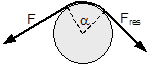 Figure 4:  Euler’s number e is an important natural constant, whose value, expressed in the decimal system and rounded, is 2.718281828. The function ex is present on all advanced pocket calculators. The deflection of the rope through an angle α of 75° and with an assumed coefficient of friction μ between the rope and the point of deflection of 0.2 as shown in Figure 4 would mean that, given a tensile force F of 100 daN, only a force Fres of 77 daN would reach the other side. The deflection angle must be included in the calculation in radians. In this example, it has a value of approximately 75 / 57.3 = 1.31 rad. The radius of the deflection point is of no significance, provided that it is not so small that the internal stiffness of the rope causes an additional loss of force. With flat lashing belts, it is perfectly possible that the deflection radius can be less than 1 cm without this edge effect having any significant impact. This threshold radius is significantly higher if a chain is used. Top of page 1.3.2 The k factor in a tie-down lashingThe Euler edge friction can be estimated simply for a traditional tie-down lashing on the basis of the lashing angle α between the lashing belt and the loading surface. As shown in Figure 5, the lashing belt is deflected twice by the same angle α. On each deflection, the pre-tensioning force FT is reduced by the factor c = e–μ‚×α. The coefficient of friction μ‘ used here applies to the friction between the belt and the cargo unit. 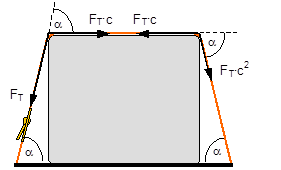 Figure 5: Loss of pre-tensioning force as a result of friction at the edges of the cargo If we assume lashing angles between 80° and 90° and coefficients of friction of 0.20 through 0.25 between the belt and the cargo, this results in values of around 0.5 for the factor c2. This means that only around half the pre-tensioning force FT applied with the tensioner is actually present on the other side. Consequently, in contrast to what is stated in the VDI 2702 Guideline (2 × FT × sinα), the sum of the vertical components of the pre-tensioning force that is actually available is only (1,5 × FT × sinα). This factor of 2 or 1.5 was dubbed the k factor, and in DIN EN 12195-1:2004 it was defined as 1.5 if tensioning was only carried out on one side and it was retained as 2 if tensioning was carried out on both sides. Because practical considerations dictate that tensioners are generally placed on one side only, this definition reduced the mathematical securing effect of a tie-down lashing by 25%, whether it was used to prevent sliding or tipping. This mathematical loss must be compensated for by a 33% increase in the number of belts if the values for friction and pre-tensioning force remain the same. This substantive increase in securing requirements is not easy to understand from today’s perspective. As far as we know, there were no systematic surveys in the form of accident analyses or statistics to support the contention that tie-down lashings compliant with the predecessor Guidelines VDI 2702 or VDI 2700, Part 2 would not have been adequate. The broad acceptance of this change in the industry in Germany can, perhaps, only be explained by the thoroughly convincing evidence of the Euler equation. Indeed, this can be demonstrated with a simple experimental measurement, and this has actually been done. As a result, the details of the original mathematical models for assessing a tie-down lashing were corrected. Nevertheless, the suitability of these models for providing a fair representation of the securing effect of a tie-down lashing must increasingly be called into question, unless they represent a deliberate attempt to achieve an increase in safety willingly paid for by a 33% increase in the number of lashing belts. Top of page 1.3.3 Mathematical models used in DIN EN 12195-1:2004The introduction of the k factor made it possible to use the transverse components of an inclined tie-down lashing in calculations. Up to that point, it was tacitly accepted that these horizontal components cancelled each other out when not subjected to a load, in much the same way as is the case with direct lashing. The lateral components of the tie-down lashing shown in Figure 6 are as follows: on the left FT × cosα and on the right FT × c2 × cosα. The effective force is always the difference, because the forces act in opposite directions. 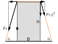 Figure 6: Components of a tie-down lashing with different pre-tensioning forces From this, we can derive the following securing effect against sliding, including the increase in friction provided by the vertical components:
Similar equations can be derived for the securing effect against tipping:
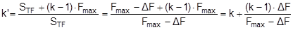
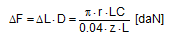
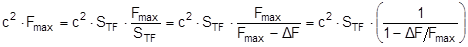
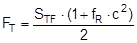
The equations show that the securing effects to the left are significantly higher and the securing effects to the right are correspondingly significantly lower. Depending on the choice of the parameters α, c, B and H, the latter can become zero or even negative. This insight alone clearly demonstrates that mathematical models such as these, even though they may be mathematically correct, do not correspond to and therefore inadequately represent the physical reality. The solution to this problem is shown in Section 1.4. The 2004 edition of DIN EN 12195-1 was less radical in its approach. The transverse components were not taken into account when formulating the securing effect against sliding. They were, however, taken into account when considering tipping, and the unfavourable scenario shown for the securing effect against tipping to the right (Equation 8) was assumed. The possibility of the securing effect becoming very small, zero or even negative, actually resulted in a formula which, under certain circumstances, could require an infinite number or even a negative number of lashing belts. This has already been dealt with comprehensively in the report „Securing cargo in road transport – Who knows the truth?“. Top of page 1.3.4 The standard tension force STFThe introduction of the k factor in EN 12195-1:2003 was not met with approval in some other parts of Europe, resulting in a certain degree of discontent. Counterarguments were presented in the form of sample calculations resulting in a nonsensically large number of tie-down lashings, together with the results of practical trials and measurements(1). Furthermore, the agreed magnitude of the k factor was contentious and remains so to this day, even though it was officially removed from EN 12195-1:2010. Above all, the sample calculations clearly demonstrate that the formulae provided are of no help in verifying the use of tie-down lashings to secure cargo against tipping. The results of the practical trials and measurements cannot and should not be confirmed or called into question in this document. The subsequent considerations with respect to the magnitude of the k factor, however, deserve some discussion, as this allows us to present some other important facts. The crucial issue is the pre-tensioning force that can be achieved in a tie-down lashing which, taken together with friction, is universally agreed to be the key factor with respect to the securing effect. The only thing the VDI 2700 Guideline Part 2 of January 2002 has to say about the desirable level of pre-tensioning force in a tie-down lashing is that it should not exceed 50% of the lashing capacity LC of the lashing equipment used, but that it should at least achieve the value determined by solving the sliding or tipping balance calculations for the pre-tensioning force FT. One sample calculation in this guideline results in a value for the minimum pre-tensioning force of 1563 daN. However, this value simply cannot be achieved with normal lashing belts. DIN EN 12195-1:2004 also simply requires values between 0.1 LC and 0.5 LC for the pre-tensioning force FT in tie-down lashings, even though the Reference to Standards section of this standard includes EN 12195-2, which was published in February 2000 and which defines a „Standard Tension Force“ (STF). This standard, which was published in February 2001 as DIN EN 12195-2 with the title „Web lashings made from man-made fibres“, for the first time specifies the pre-tensioning force that can be achieved on lashing belts using normal ratchet tensioners and how to determine this using a uniform testing method. It was only in the draft of the revised version of VDI 2700, Part 2 of January 2002 and in DIN EN 12195-1:2011 that this STF value was recommended as the pre-tensioning force to be used in the balance calculations. This has a consequence for the k factor. The scenario shown in Figure 5 assumes that the pre-tensioning force FT is established using a tensioning device that increases the tension constantly, such as a turnbuckle. However, the normal means of tensioning web lashing belts are ratchet tensioners with a lever. When the belts are tensioned, this lever is operated until a hand force(2) of no more than 50 daN is reached. The ratchet lever is then relaxed until the ratchet pawl engages in the last tooth of the winding drum over which the pawl has passed. This relaxation causes the pre-tensioning force in this part of the belt to fall slightly. The result is that the pre-tensioning force on the side opposite to that being tensioned is higher than would normally be expected according to the Euler equation in respect of the remaining pre-tensioning force on the side being tensioned. One recent publication(3) takes this typical modus operandi for ratchet tensioners as an argument for using a k factor of 2, which equates to the same pre-tensioning force on both sides of the belt. Initially, the argument appears to be sound. But, on closer inspection, the scope for such balancing of pre-tensioning force is small if the ratchet tensioners are used as intended in compliance with the standard. The standard tension force STF printed on the label of any standardized belt is determined for each belt prototype using a testing method described in the DIN EN 12195-2:2001 standard. This method simulates practical usage of the belt in a standardized testing device in which the tensioning lever is eased after tensioning up to the standard hand force SHF of 50 daN until the pawl engages with the last tooth of the winding shaft that it passed over. The statistical effect of the resulting loss in force from multiple repetitions of the test with the belt in different positions is that, depending on the gap between the teeth, only around 70% to 90% of the maximum possible pre-tensioning force that can be achieved with the SHF can be determined to be present as the STF. This testing method can be modelled mathematically as follows: Tensioning the belt with the standard hand force SHF generates the initial force Fmax on the side being tensioned and the associated residual force (k – 1) × Fmax on the opposite side. Subsequent locking of the tensioning lever causes the force on the side being tensioned to be reduced by ΔF. The residual force is the standard tension force STF = Fmax – ΔF. This allows us to calculate the new factor k‘ with reference to STF.
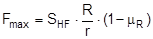
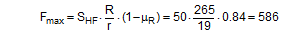
We can immediately see that this corrected value k‘ must be greater than k. It tends towards larger values for ratchet tensioners with 10 or 11 teeth on the ratchet wheel of the winding axis and towards lower values for those with 18 or 20 teeth. In order to estimate the magnitude of k, it must be possible to determine the values Fmax and ΔF with at least some degree of precision. The initial pre-tensioning force Fmax is determined from the standard hand force and the transformation ratio of the ratchet minus any friction in the ratchet mechanism.
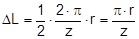
The relaxation as the pawl engages with the last tooth of the winding shaft leads to an elastic shortening of the belt by a length ΔL, whose statistical average is derived by multiplying the radian measure of half a tooth pitch by the effective winding radius. This length is:
The elastic constant D required to calculate the loss of force in the section of the belt with a length L is estimated from the elastic elongation of approximately 4% on reaching the LC value as reliably given for high-quality belts. Thus: D = LC / (0,04 × L). The length L must also be specified in mm here.
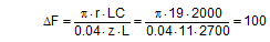
Fmax = maximum pre-tensioning force that can be achieved with standard hand force without relaxation [daN] R = lever length of the ratchet [mm] r = effective radius of the winding shaft with approximately 2 layers of [mm] μR = coefficient of friction in the ratchet mechanism STF = standard tension force [daN] SHF = standard hand force = 50 [daN] ΔL = relaxation of the belt when the pawl engages [mm] ΔF = reduction in pre-tensioning force after the pawl engages [daN] z = number of ratchet teeth D = elastic constant of the belt [daN/mm] LC = lashing capacity of the belt [daN] L = length of the section of belt under consideration [mm] The average of an analysis of 30 different ratchet tensioners from different manufacturers resulted in a value of k‘ = 1.60 for an initial value k = 1.5. 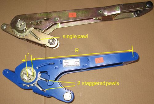 Figure 7: Ratchet tensioners The following figures, also assuming a value of k = 1.5, represent a typical example: Certified STF = 480 daN; lever length R = 265 mm; winding radius r = 19 mm; number of teeth z = 11; lashing capacity LC = 2000 daN; assumed length of the belt on the side being tensioned L = 2700 mm; coefficient of friction in the ratchet μR = 0.16; standard hand force SHF = 50 daN.
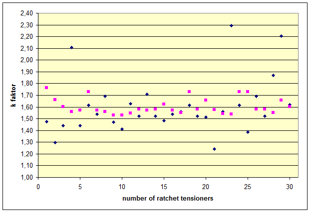 Figure 8: k‘ values for ratchet tensioners Figure 8 shows the k‘ values determined for 30 different ratchet tensioners. The calculation assumes a nominal k factor of 1.5, derived from a lashing angle α = 90° and a coefficient of friction between the belt and the cargo μ = 0.22. The black diamonds indicate the k‘ values in relation to the certified STF values. The red squares indicate the k‘ values with reference to the STF values calculated using the mathematical model. In both cases, the average result was 1.61 as stated above. The k‘ values derived with reference to the certified STF values show a far greater spread. This is peculiar and could be the result of test methods not being employed correctly. In the first place, the argument presented for a uniform k factor of 2 in the publication mentioned above has been put into perspective by the actual process involved in tensioning a belt, and has been disproved as a general rule. Nevertheless, significant errors when evaluating the effectiveness of a tie-down lashing can arise if the certified standard tension force STF determined is too small as a result of the inadequately described test method(4) in DIN EN 12195-2:2001. If you correlate the values that can be achieved in practice using standard hand force with this excessively small value, the fact is that k factors considerably larger than 2 can result, but these are not accepted by the standard. Nevertheless, the value of 2.8 for k given in the publication mentioned above is likely to have been an isolated extreme example where the certified STFwas too low and the ratchet tensioner was used to tension the belt beyond the range permitted by the standard. Top of page 1.3.5 Use of the friction between the lashing equipment and the cargoThe idea of making use of the friction between the belt and the cargo for securing the cargo is nothing new and was taken up in the German VDI 2702 Guideline as early as May 1990. Section 5.2 of this guideline dealt with inclined, transverse lashing of cuboid cargo units, and the second example described a crate that was liable to tip and had no lashing points being secured by two lashing belts that were not attached to the crate, but each of which instead completely encircled it. These loop lashings end up on both sides of the crate at an angle of α and appear to be direct lashings, but are connected to each other by means of Euler edge friction. The entire contact angle is 2× (α + π). 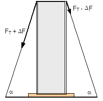 Figure 9: Securing cargo with loop lashings (as per VDI 2702) The purpose of this example was to show that the lashing force required on one side presupposes a residual lashing force on the other side. This residual lashing force correlates to the required lashing force according to Euler’s friction loss. The analysis of the example that then follows, however, contains a minor error in the balance equation for tipping, but we shall not go into that here. The presentation of the scenario assumes that tensioning equipment initially applies a specific, equal pre-tensioning force to both sides of the configuration to be secured. When the assumed load is applied, this force increases on one side and decreases on the other side until the forces reach the stated ratio. The pre-tensioning force initially applied must be large enough to balance the sliding or tipping calculation. There is no mention of the fact that the assumed opposing changes to the pre-tensioning force on the two sides presupposes that the cargo unit moves slightly. This was presumably a tacit assumption, because the example was presented as a special case of direct securing. This classification is perfectly understandable if you accept that „the lashing equipment is secured to the cargo by friction“. And it is also obvious that a higher level of friction between the encircling lashing equipment and the cargo unit will enhance the securing effect. However, the fact that it is normal that a pre-tensioning force is applied to tie-down lashings on one side only, combined with the use of the k factor and the mathematical model that accounts for vertical forces only, led to the often-repeated dogma that friction should be kept as low as possible at the edges of the cargo. This principle is not wrong, but may, on closer investigation, need to be qualified, i.e. it may not apply under certain circumstances. „Frictional engagement“ between the tie-down lashing and the cargo will play a key role in the next section. Top of page 1.4 Actual securing effect of a tie-down lashingThis discussion will present the complete securing effect of a tie-down lashing in mathematical form on the basis of the list in Section 1.1, excluding the secondary effects of compaction and the attenuation of vibrations. It is assumed that the tie-down lashing uses a synthetic web belt with a ratchet tensioner on one side and is secured laterally across the vehicle. The dimensions of the cargo match the lashing angles and the width of the vehicle (approx. 2.5 m). The purpose of this presentation is to compare different mathematical models and assess any possible simplifications. When comparing mathematical models, the same coefficient of friction between the cargo and the loading surface is assumed, in order to assess the securing effects of the transverse components without any falsification. 1.4.1 Pre-tensioning forces in the initial situationIn the calculations in the sections below, it is assumed that the tie-down lashing under consideration has been tensioned on one side with the pre-tensioning force STF. Section 1.3.4 demonstrated that this pre-tensioning force STF is to be regarded as the difference between the maximum force Fmax that can be achieved with a hand force of 50 daN and the loss in force ΔF, while the opposite side remains tensioned with a pre-tensioning force of c2 × Fmax. This pre-tensioning force is also expressed with STF. The factor c2 stands for Euler’s friction loss.
The expression in brackets on the right is the factor by which the pre-tensioning force on the opposite side relative to the standard tension force STF is increased when STF is defined as the pre-tensioning force after the ratchet tensioner has been relaxed, as described in detail in Section 1.3.4. This value is referred to below as the „ratchet factor“ or fR. It is directly dependent on the quotient ΔF/Fmax, and is always greater than 1. Note: The factor fR accords with the correction of the k factor detailed in Section 1.3.4. It is simply a different approach to the same issue. The following relationships exist:
The k factor and k‘ factor represent the pre-tensioning force on the two sides. However, treatment of the transverse components on the two belt sections becomes clearer if they are regarded separately. For this reason, they are included in the calculation as STF and In the calculations in the following sections it is further assumed that the originally differing pre-tensioning forces on the two sides have become equalized as the result of slight lateral accelerations. Such equalization is not, as is commonly simply assumed, the result of vertical vibration of the vehicle, but rather the result of lateral movements of the cargo, primarily in the form of deformation. This assumption that the initial situation is symmetrical simply facilitates comprehension of the calculations. It is not a strict technical requirement. Given these assumptions, the following pre-tensioning force is present on both sides:
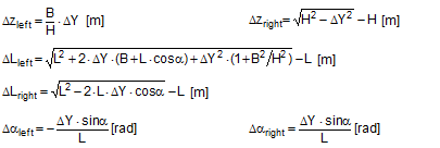
FT = pre-tensioning force after equalization [daN] STF = standard tension force [daN] Fmax = maximum pre-tensioning force that can be achieved with standard hand force without relaxation [daN] ΔF = reduction in pre-tensioning force after the pawl engages [daN] c = Euler factor (c = e–μG×α) α = vertical lashing angle [rad] μG = coefficient of friction between the belt and the cargo fR = ratchet factor The value of fR depends on a large number of parameters (see Section 1.3.4). To allow a generally applicable assessment of a tie-down lashing, it is chosen in such a way that there is extremely little chance that the value attained in practice will ever fall below this value. The random sample of 30 ratchet tensioners used in Section 1.3.4produces the values for fR shown in Figure 10 for belt section lengths of 2.0 m. The value fR = 1.2 is used below. 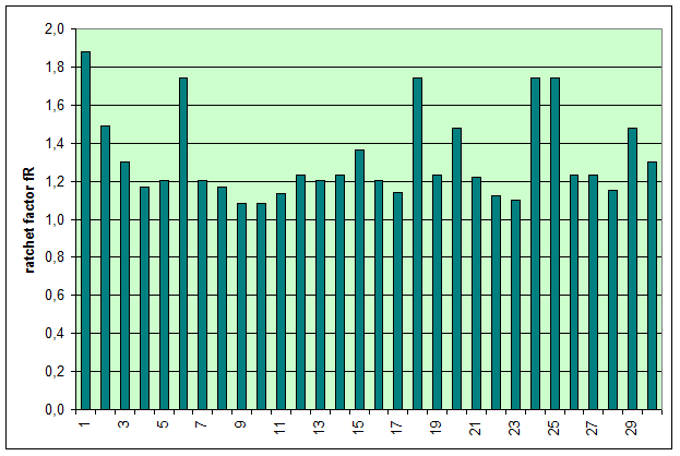 Figure 10: Ratchet factors for a random sample with belt section length of 2 m Top of page 1.4.2 Changes to the lashing lengths and lashing anglesIf significant external forces act on secured cargo, the cargo will move slightly in the direction of these forces. This movement can take the form of displacement (sliding) or deformation (plastic and/or elastic deformation). In the case of deformation, a distinction must be made between „traditional“ frame deformation and deformation resulting from layer displacement (referred to below simply as „layer displacement“). The height of the cargo is unaffected by displacement and layer displacement. It decreases slightly in the event of frame deformation. Another way in which cargoes move is when a cargo that is liable to tip tilts if its stabilizing moment is smaller than the tilting moment generated by the external force. If we wish to determine the securing effect of a tie-down lashing as exhaustively as possible, it is important that any changes to the lengths and angles of the various sections of the belt that are caused by such movements are taken into account. The total change in the length of the belt is also significant, because this entails a change to the overall level of pre-tensioning force in the tie-down lashing. It is sufficient to adopt a simple linear approach to calculating changes to the angles, because they only have a major influence on the securing effect if the lashing angles are large, and a linear approach is adequate for such large angles in particular. The reverse is true with respect to changes in length. They are calculated precisely using Pythagoras‘ theorem. This results in correspondingly complex formulae. Lateral movement crosswise relative to the vehicle When the cargo moves laterally relative to the vehicle, the edges of the cargo units shift by the short distances ΔY and ΔZ. The distance ΔY is used below as an input and reference parameter. The lashing angle α and the distance ΔY are treated as absolute values in the formulae. In the case of displacement and layer displacement in a transverse direction relative to the vehicle, ΔZ = 0 (Figure 11).
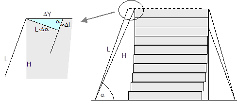 Figure 11: Δα and ΔL on displacement or layer displacement in a transverse direction relative to the vehicle In the case of frame deformation in a lateral direction relative to the vehicle, ΔZ is a small, negative value (Figure 12).
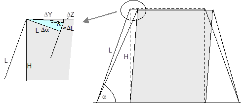 Figure 12: Δα and ΔL on frame deformation in a lateral direction relative to the vehicle In the event of tilting (Figure 13), a positive value for ΔZ results on the left. On the right, the movement of the edge of the cargo corresponds to that in the event of frame deformation.
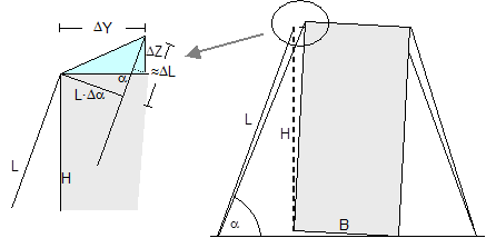 Figure 13: Δα and ΔL on the left in the event of tilting in a lateral direction relative to the vehicle Movement in a longitudinal direction relative to the vehicle When the cargo moves longitudinally relative to the vehicle, the edges of the cargo unit shift by the short distances ΔX and ΔZ. Because the belt runs in a direction perpendicular to that in which the cargo moves, it only moves with the cargo within the limits permitted by the friction available. The distance ΔX is used below as an input and reference parameter. Any change to the length ΔL of the belt is always positive and equal on both sides of the cargo. The change to the lashing angle α is so slight that it can be ignored when calculating the securing effect. In the event of displacement and layer displacement in a longitudinal direction relative to the vehicle (Figure 14), the following applies to both sides:
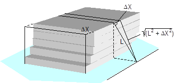 Figure 14: ΔL on displacement or layer displacement in a longitudinal direction relative to the vehicle In the event of frame deformation in a longitudinal direction relative to the vehicle (Figure 15), Δz is a small, negative value as described in Equation (18) for lateral frame deformation. The geometrical result is that the length of the belt does not change in any way. The following applies to both sides:
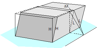 Figure 15: ΔL on frame deformation in a longitudinal direction relative to the vehicle In the event of tilting (Figure 16), a positive value for ΔZ results on both sides. The following relationships apply on both sides:
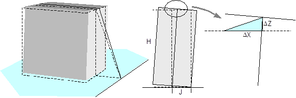 Bild 16: ΔL beim Ankippen längs zum Fahrzeug Top of page 1.4.3 Elasticity of lashing beltsThe changes in the lengths of the belt sections lead to changes in the pre-tensioning forces. This applies both to the left and right belt sections and to the overall level of pre-tensioning force. These changes to the forces are included in the calculation of the securing effect. As indicated in Section 1.3.4, the term „elastic constant“ is used in this context. The elastic constant D makes it possible to calculate the change in force ΔF of a long elastic body directly from the change in length ΔL.
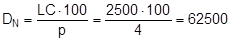
Lashing belts made from synthetic fibres behave with sufficient elasticity within their load range up to LC, and in simplified terms, linearity can be assumed. The tested belt shown in Figure 10 was certified as having an elastic stretch p of 3.75% on reaching its LC of 2500 daN. A specification such as this firstly makes it possible to determine the „nominal“ elastic constant DN that can be defined for a standard length, for instance one meter.
The specific elastic constant can then be derived for any belt length L.
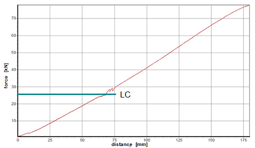 Figure 17: Load/stretch chart for a 50 mm polyester belt (source: Dolezych) The load/stretch curve is somewhat flatter at the bottom of the load range. Therefore, the calculations in the sections below use a fixed value p = 4% for the stretch percentage(5).
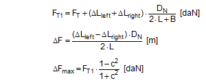
Top of page 1.4.4 Securing force in a lateral direction relative to the vehicleTo start with, the changes in length ΔLlinks and ΔLrechts as determined in Section 1.4.2 are used to determine the overall change in length of the belt resulting from the given type of movement. In the case of displacement and layer displacement, this change is positive with a maximum at a lashing angle of 90°. As a consequence, the pre-tensioning force FT calculated on the basis of Equation (15) rises. In the case of frame deformation, the overall change in length is a small negative value, tending towards zero at a lashing angle of 90°. The pre-tensioning force FT drops accordingly. This change in force is calculated in a simplified form using the entire length of the belt. FT1 is the corrected pre-tensioning force.
The potential increase in force on the left or decrease in force on the right in the free sections of the belt are calculated using the length changes ΔLlinks and ΔLrechts.
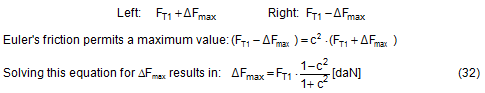
Up to lashing angles of approximately 85°, these changes in force are generally so large that the belt slides over the cargo. This results in an upper limit for the change in force ΔF determined by Euler’s friction between the belt and the cargo unit. This upper limit is calculated below on the basis of the following boundary scenario.
The complete securing effect is made up of SE1 = the increase in friction from the vertical components of the forces in the left and right sections of the belt and of SE2 = the difference between the horizontal components of these forces.
It is obvious that the maximum value for ΔF from Equation (32) must be used in Equations (33) and (34) and subsequently also in Equation (35). 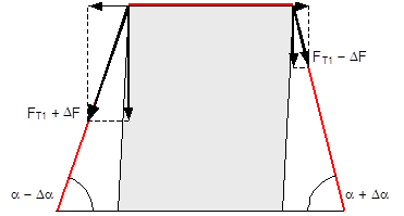 Figure 17a: Securing effect resulting from forces in a lateral direction relative to the vehicle Because Δα is a small angle, the following can be set with sufficient accuracy: cosΔα = 1 and sinΔα = Δα. This simplifies the equation for the overall securing effect.
For a lashing angle α = 90°, the equation is further simplified with sinα = 1 and ΔF = 0.
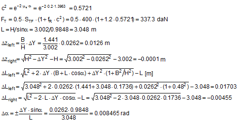
SE = overall securing effect [daN] μL = coefficient of friction between the loading surface and the cargo FT1 = equalized, corrected pre-tensioning force [daN] according to Equation (30) ΔF = change to pre-tension force [daN] according to Equation (31), limited by Equation (32) α = initial lashing angle [°] Δα = change to lashing angle [rad] according to Equation (17) To demonstrate this, we shall calculate an example on the assumption that we are dealing with displacement or layer displacement. The height and width of the cargo match the width of the vehicle of 2.5 m. The input parameters are as follows:
As a comparison, the securing effect is calculated in accordance with VDI 2702 as it was in Equation (1): 
The possible mean value for ΔF of around 600 daN given a lateral movement of ΔY = 0.1 m is almost 6 times the limit value of 108.5 daN used for the actual calculation. This means that the limit value would be reached after a lateral movement of less than 2 cm with the given lashing angle of 80°. The securing effect changes with the lashing angle. Because the width of the loading areas of commercial vehicles is restricted to around 2.5 m, small lashing angles only occur with low cargoes. The following plausible cargo dimensions have been chosen for the examples below showing the securing effects across a range of lashing angles between 45° and 90°:
Figure 18 shows the curves for the securing effects compared with the curves resulting from the simplified mathematical models contained in VDI 2702, DIN EN 12195-1:2004 and DIN EN 12195-1:2011. All five curves are subject to the same conditions as in the example for α = 80° that we calculated above. The actual securing effect reaches its maximum at a lashing angle of approximately 65° to 70°. Only at an angle α of approximately 88° do the changes to the lengths of the belt sections caused by movement become so small that the favourable Euler force ratio can no longer achieve its maximum value. Instead, as of approximately α = 87°, the lateral component on the right starts to have a securing effect. These changes to the way in which the securing effect works cause a slight kink in the curve at this point. The comparison with the mathematical models demonstrates that the actual securing effect across a wide range is actually greater than indicated by the earlier model in the VDI 2702 Guideline. The reduction caused by the introduction of the k factor in DIN EN 12195-1:2004 is considerable. The justification that this necessarily took account of physical facts is invalid, because these facts were only interpreted from a one-sided perspective. 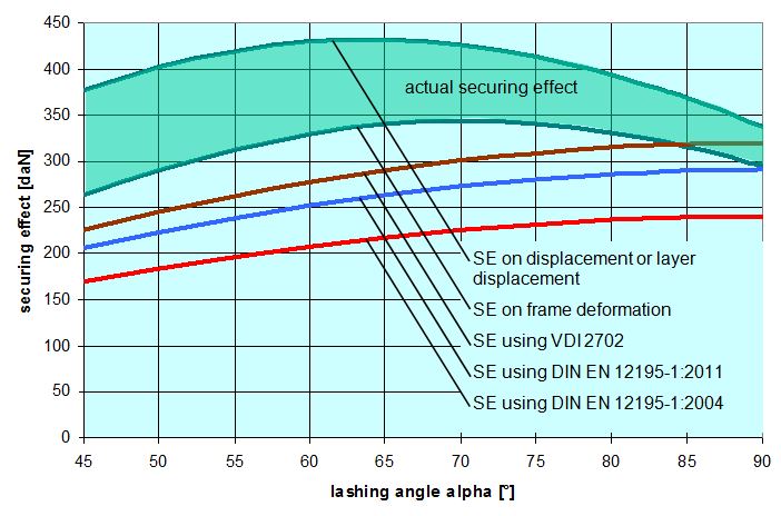 Figure 18: Securing effect of lateral forces, comparison of mathematical models Top of page 1.4.5 Securing force in a longitudinal direction relative to the vehicleHere also the changes in length on both sides ΔL as identified in Section 1.4.2 will be used to identify the overall change in length of the belts for the given type of movement. In the case of displacement and layer displacement, this change is positive. As a consequence, the pre-tensioning force FT calculated on the basis of Equation (15) rises. This change in force is calculated in a simplified form using the entire length of the belt. FT1 is the corrected pre-tensioning force.
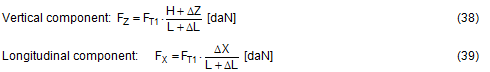
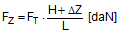
In the case of frame deformation, the overall change in length is zero. The pre-tensioning force is unchanged at FT1 = FT. In the case of frame deformation, however, there is a vertical movement ΔZ. 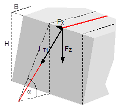 Figure 19: Securing effect resulting from forces in a longitudinal direction relative to the vehicle The overall securing effect is made up of the vertical components on both sides FZ, multiplied by the coefficient of friction μL, and the longitudinal components FX on both sides.
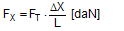
There is an upper limit for the longitudinal component ΔX determined by the friction between the belt and the cargo. The deflected belt exerts a force FK on the edge of the cargo that is the resultant force from the pre-tensioning force of the two neighbouring belt sections. Because of the uneven load distribution on the two sides of the edges, we shall calculate conservatively using FT instead of FT1. 
The upper limit of the longitudinal component depends on the coefficient of friction between the belt and the cargo. 
The securing effect of the tie-down lashing in a longitudinal direction is calculated using these parameters. 
An example will be calculated for displacement or layer displacement. The input parameters are as follows:
In this case also, the value of the securing effect calculated according to VDI 2702 is significantly lower. 
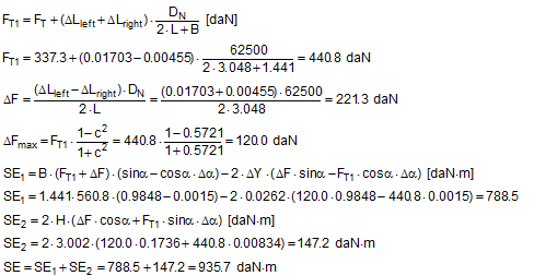
As expected, in the event of frame deformation, the actual securing effect is lower, because there is no elongation of the belt. The securing effects change with the lashing angle. Figure 20 uses the same plausible values for α, H and B as Section 1.4.4 to show the securing effect curves compared with those derived from the simplified mathematical models in VDI 2702, DIN EN 12195-1:2004 and DIN EN 12195-1:2011. All five curves are subject to the same conditions as in the example for α = 80° that we calculated above. Comparison with the mathematical models shows that, in a longitudinal direction also, the actual securing effect is considerably greater than indicated by the simplified mathematical models. In order to produce a value, the magnitude of which is comparable with the securing effect in a lateral direction, the longitudinal movement of the cargo ΔX was changed from 0.10 m to 0.12 m. The difference between the securing effect to the rear and the securing effect to the front that appears in DIN EN 12195-1:2011 seems peculiar, because there is no physical basis for it. In fact, it is said that when they adopted this definition, the committee responsible was attempting to compensate for the different assumptions made across Europe with respect to the loads arising from forces acting in a longitudinal direction to the front. 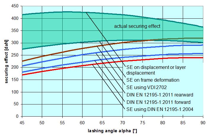 Figure 20: Securing effect of longitudinal forces, comparison of mathematical models Top of page 1.4.6 Securing moment in a lateral direction relative to the vehicleIt is only necessary to check that a tie-down lashing is suitable for securing cargo against tipping if the stability of the cargo unit is insufficient. Put simply, this applies to units whose contact width B is less than 60% of their height H. Taken together with the width of the loading area of approximately 2.5 m, and a maximum cargo height of approximately 3 m, this restricts the plausible lashing angles to a range between around 45° to a maximum of 83°. The following plausible cargo dimensions were chosen to demonstrate the securing effect against tipping over this range. They are based on B = 0.48 × H:
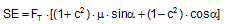
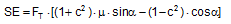
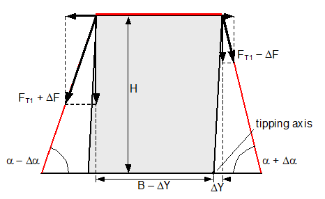 Figure 21: Securing effect resulting from moments in a lateral direction relative to the vehicle In order to account for movement of the cargo when formulating the securing moments, it is necessary that the lever B of the left-hand vertical component is reduced by ΔY and also that the right-hand vertical component with the lever ΔY has a tilting effect (Figure 21). These represent small reductions in the securing effect compared with the simplified mathematical models provided in the standards. However, the following calculations show that these reductions in the securing effect against tipping in a lateral direction remain minimal, because only small values of ΔY are necessary in order to establish the desired lateral components of the pre-tensioning forces. The complete securing effect against tipping is made up of SE1 = moment from the vertical components of the forces in the left and right sections of the belt and of SE2 = moment from the difference between the horizontal components of these forces. Die Berücksichtigung einer Ladungsbewegung bei der Formulierung der Sicherungsmomente verlangt, dass der Hebel B der linken Vertikalkomponente um ΔY verkleinert wird, und dass außerdem die rechte Vertikalkomponente mit dem Hebel ΔY kippend wirkt (Bild 21). Das sind kleine Abzüge in der Sicherungswirkung gegenüber den vereinfachten Rechenmodellen in den Richtlinien und Normen. Es zeigt sich allerdings in den folgenden Berechnungen, dass diese Abzüge bei der Kippsicherung in Querrichtung verschwindend klein bleiben, weil nur kleine Beträge von ΔY erforderlich sind, um die erwünschten Querkomponenten der Vorspannkräfte aufzubauen. Die vollständige Sicherungswirkung gegen Kippen setzt sich aus SW1 = Moment aus den Vertikalkomponenten der Kräfte in den Gurtanteilen links und rechts und aus SW2 = Moment aus der Differenz der Horizontalkomponenten dieser Kräfte zusammen. 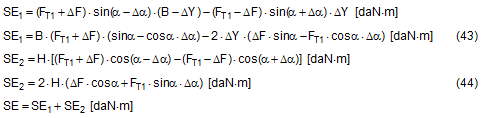
SE = overall securing effect [daN×m] B = contact width of the cargo unit [m] H = height of the cargo unit [m] FT1 = equalized, corrected pre-tensioning force [daN] according to Equation (30) ΔF = change to pre-tension force [daN] according to Equation (31), limited by Equation (32) ΔY = lateral movement of the top surface of the cargo [m] α = initial lashing angle[°] Δα = change to lashing angle [rad] according to Equation (17) In these derivations, simplifications have as before been made by making Δα on the left and on the right equal, and by using cosΔα = 1 and sinΔα = Δα. The subtrahend in SE1 „(FT1−ΔF) × sin(α + Δα) × ΔY“ is not required if the cargo unit only slides, because the tipping edge on the bottom of the cargo also shifts sideways. However, this is rather unlikely, as the cargo unit here is, by definition, liable to tip and is therefore more likely to tilt than to slide. We shall calculate an example of tilting by 0.5° as a reactive movement. The input parameters are as follows:
As a comparison, the securing effect is calculated in accordance with VDI 2702:
This comparison shows that the actual securing effect after the cargo unit has tilted slightly is considerably greater than the securing effect calculated according to the recommendation, which is now regarded as outdated, in the VDI 2702 Guideline of 2000. Conversely, this means that if securing is carried out according to this guideline, the cargo would probably not tip at all, because the other movements of the cargo such as sliding, layer displacement or frame deformation would alone be sufficient to achieve the necessary securing effect. This probable behaviour will be verified below using the following conservative assumptions: Der Vergleich zeigt, dass die tatsächliche Sicherungswirkung nach einem geringfügigen Ankippen der Ladungseinheit erheblich größer ist als die Sicherungswirkung nach der inzwischen als überholt geltenden Empfehlung der Richtlinie VDI 2702 von 2000. Das bedeutet im Umkehrschluss, dass es bei einer Auslegung der Sicherung nach dieser Richtlinie wahrscheinlich überhaupt nicht zu einem Ankippen kommen wird, weil die übrigen Ladungsbewegungen wie Rutschen, Plattenverschub oder Rahmenverschub allein ausreichend sind, um die benötigte Sicherungswirkung zu erzielen. Dieses wahrscheinliche Verhalten wird nachstehend unter folgenden konservativen Annahmen überprüft:
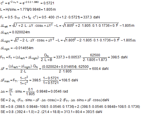
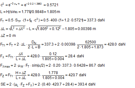
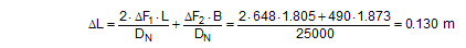
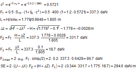
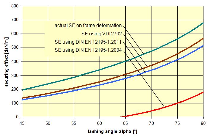 Figure 22: Securing effect of lateral moments, comparison of mathematical models The curves in Figure 22 show that despite the conservative assumptions made, the actual securing effect exceeds that given by all the current mathematical models. The model given in DIN EN 12195-1:2004 is particularly striking. Lashing angles of less than 64° and the ratio B : H = 0.48 used here result in negative securing effects, i.e. in purely mathematical terms, the use of belts would increase the risk of tipping. This mathematical model is completely useless. The lateral movement ΔY required to achieve the actual securing effect shown in Figure 22 is just under 2 mm when α = 45° and increases to just under 26 mm when α = 80°. These values are significantly smaller than the movements required with a direct lashing in order to achieve the lashing capacity LC of the lashing equipment as normally determined in the balance calculation. This means that tilting is not required. Even a completely rigid cargo unit that cannot itself be deformed in any way can achieve the necessary lateral movement ΔY by a small amount of sliding and/or deformation of the loading surface without tilting. Top of page 1.4.7 Securing moment in a longitudinal direction relative to the vehicleA tie-down lashing placed laterally relative to the vehicle can act in the same way against tipping in a longitudinal direction as a direct lashing. Traditionally, direct lashings are assessed in such a way that their lashing capacity LC is used in a balance calculation. However, this approach presumes that the securing equipment stretches elastically to such an extent that the securing force increases from the initial pre-tensioning force FT up to the rated lashing capacity LC. The amount of stretch required to achieve this can amount to several centimetres for a tie-down lashing and, in this case, where we are talking about securing cargo against tipping, is only achieved if the cargo tilts. Displacement and/or deformation are hardly sufficient for this scenario. Tilting of this magnitude, however, is associated with risks resulting from dynamic effects. In the example below, we estimate the potential magnitude of such tilting on the basis of a calculation. Tilting with a securing force = LC A homogeneous cargo unit with a weight W = 3200 daN, a width B = 1.873 m and a height H = 1.778 m is located transversely on the vehicle and secured with a lateral tie-down lashing. The tie-down lashing is placed halfway along the length of the cargo unit. The distance to the front and rear tipping axis J = 0.444 m in both directions. The lashing angle α = 80° on both sides. The lengths of the free belt sections L = 1.805 m on both sides. 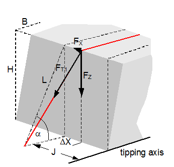 Figure 23: Securing effect resulting from moments in a longitudinal direction relative to the vehicle The vertical components of the tie-down lashing that secure the cargo against tipping act on the lever J to the tipping axis. The moment balance calculation for tipping to the front on the basis of VDI 2702 is:
This change in length is distributed across both sides with a magnitude of 0.065 m on each side and results in the cargo moving upwards under the tie-down lashing by 6.6 cm, corresponding to a tilt of approximately 8.5°. Changes to the tilting geometry and the moment of rotational inertia of the tilting cargo during an emergency braking manoeuvre can cause this value to rise considerably, so that it seems inadvisable to interpret the necessary force as the lashing capacity LC. It is presumably for this reason that the VDI 2702 Guideline of May 1990 and the VDI 2700, Part 2 Guideline of November 2002 include a mathematical model for this situation, in which a pre-tensioning force that should be limited to 50% of the lashing capacity LC is assumed as the securing force. The DIN EN 12195-1:2011 standard also proposes the pre-tensioning force STF (or a measured value) as the securing force and also introduces a safety factor into the calculation. This factor is 1.25 in the event of loads in the direction of travel and 1.1 in the event of loads against the direction of travel. The interim standard DIN EN 12195-1:2004 does not contain any suggestions for this scenario. The mathematical models presented do not assume any reactive movement on the part of the cargo. Neither do they deal mathematically with any loss of friction if tensioners are used on one side only. Because this does not reflect reality, the actual securing effect of the tie-down lashing will be compared with the simplified mathematical models. Securing effect with pre-tensioning force We assume a movement of the cargo of the same magnitude as was used to present the securing forces in a longitudinal direction. The type of movement assumed is either frame deformation or tilting. Sliding is less probable because of the imminent risk of tipping and layer displacement is not considered for practical reasons. In the event of frame deformation, the length of the belt does not change, and the pre-tensioning force does not, therefore, increase (Section 1.4.2). The force FT determined in Equation (15) is unchanged.
In addition to the longitudinal movement ΔX, there is also a small vertical movement of the top surface of the cargo ΔZ according to Equation (24). In this case, the value of ΔZ is negative.
According to Equation (41), the upper limit of the longitudinal component is:
We now calculate the securing effect of the tie-down lashing against tipping in a longitudinal direction.
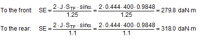
SE = overall securing effect [daN×m] J = lever of the vertical components of the tie-down lashing to the tipping axis [m] FT = equalized pre-tensioning force according to Equation (15) [daN] FZ = vertical component of FT [daN] FX = horizontal component of FT [daN] H = height of the cargo unit [m] L = length of the free belt section [m] ΔX = longitudinal movement of the top surface of the cargo [m] ΔZ = vertical movement of the top surface of the cargo [m] μB = coefficient of friction between the belt and the cargo α = lashing angle [°] We shall perform an example calculation. The input parameters are as follows:
As a comparison, the securing effect is calculated in accordance with DIN EN 12195-1:2011:
This shows that under the assumption that the type of movement is frame deformation, the actual securing effect is smaller than that calculated by the mathematical model in DIN EN 12195-1:2011 for loads acting to the rear, but larger for loads acting to the front. We have already commented on this peculiarity at the end of Section 1.4.5. If the actual securing effect of a tie-down lashing that has been dimensioned for loads to the rear in accordance with the mathematical model above (i.e. weaker) is not able to withstand the load, the cargo unit will inevitably tilt as soon as its increasing inner rigidity prevents any further deformation. It is perfectly possible that this can happen even if ΔX < 0.1 m. We shall now calculate the same example using a tilting value of ϒ = 0.5° as a reactive movement.
This result exceeds both mathematical models given in DIN EN 12195-1:2011, which means that the cargo can be expected to tilt by less than 0.5° under the given conditions. The calculated securing effects change with the lashing angle. The results shown in Figure 24 show that the mathematical models given in DIN EN 12195-1:2011 are sufficient. Nevertheless, when securing cargo against tipping to the rear, a small amount of tilting < 0.5° can be expected if the securing is dimensioned without any significant reserves. 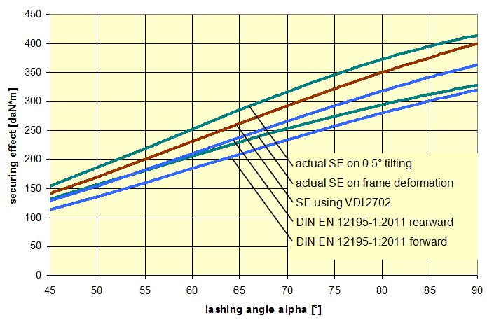 Figure 24: Securing effect of longitudinal moments, comparison of mathematical models Top of page 1.4.8 Influence of the coefficient of friction between the lashing material and the cargoThe mathematical models used to represent the actual securing effect of a tie-down lashing depend to a considerable extent on the pre-tensioning force FT. This pre-tensioning force is based on the standard tension force STF of the belt used and on the transmission coefficient k, which was used in the form (1 + c2) in the calculations above. A large value for c2 assumes a low coefficient of friction between the belt and the cargo. On the other hand, the securing effect of a tie-down lashing benefits from the difference between the transverse components of the pre-tensioning forces on the two sides when loaded in a lateral direction relative to the vehicle, in particular if the lashing angles are small. This difference increases with a large coefficient of friction between the belt and the cargo. This applies both to the securing forces and to the securing moments. In the event of a load in a longitudinal direction, the first of these influences is the dominant one, namely a low coefficient of friction between the belt and the cargo. This somewhat confusing situation will be clarified in the diagrams below. 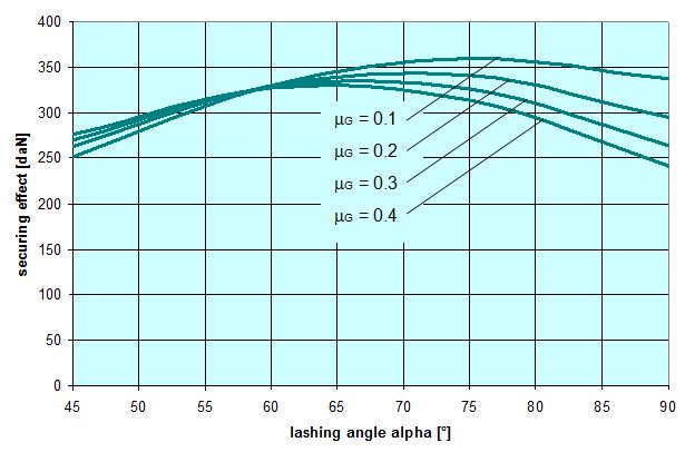 Figure 25: Securing effect of lateral forces, influence of the coefficient of friction between the belt and the cargo Figure 25 provides an example showing that the coefficient of friction between the belt and the cargo should be kept to a minimum in order to maximize the securing effect in the form of transverse forces. This applies especially in the event of large lashing angles. In the event of small lashing angles of less than 70°, the significance of this influence is reduced and, indeed, is inverted slightly for lashing angles of less than 60°. However, because small lashing angles are only technically feasible for low, narrow cargo units, such angles indicate a securing scenario in which direct securing would possibly be the better option. This means that as a basic principle the coefficient of friction between the belt and the cargo should be kept as low as possible with the large lashing angles that are usual in day-to-day practice. This is achieved using suitable edge protectors. In very specific circumstances with small lashing angles, it can, however, be better to place anti-slip material under the belts at the edges of the cargo. 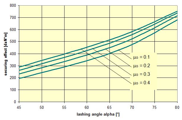 Figure 26: Securing effect of lateral moments, influence of the coefficient of friction between the belt and the cargo Figure 26 shows the opposite effect of the coefficient of friction between the belt and the cargo if the tie-down lashing is to be used to secure the cargo against tipping. A large coefficient of friction favours the transverse components acting with the larger lever H to such an extent that it overrides the overall lower level of pre-tensioning force. The smaller the ratio B : H, i.e. the more liable a cargo unit is to tip, the greater this effect. In cases such as this, anti-slip material should be placed under the lashing belts. These comments should not distract from the fact that a direct lashing would possibly be the better option for securing against tipping in such cases. Figures 27 and 28 show that the securing effects in the form of both forces and moments in a longitudinal direction relative to the vehicle certainly benefit from a low coefficient of friction between the belt and the cargo. This reinforces the basic recommendation that low-friction edge protectors should be used. Because longitudinal components of the lashing forces are also intended to be transmitted to the edge of the cargo when securing against longitudinal forces, it is advisable that the edge protectors should feature suitable beads or protrusions to prevent the belt from slipping in a longitudinal direction. This is regularly the case with narrow edge protectors, simply to prevent the belt from slipping off the side of the protector. 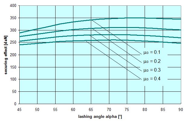 Figure 27: Securing effect of longitudinal forces, influence of the coefficient of friction between the belt and the cargo 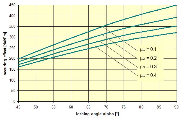 Figure 28: Securing effect of longitudinal moments, influence of the coefficient of friction between the belt and the cargo Top of page 1.5 Practical implementationThe considerations and calculation methods presented in Section 1.4 representing the actual securing effect of a tie-down lashing and covering the four requirements „preventing cargo from sliding laterally and longitudinally“ and „preventing cargo from tipping laterally and longitudinally“ are scarcely suitable for practical use. They could be used with a calculation program for one-off calculation of standardized securing concepts. But even then, it would be advisable to carry out practical trials in order to calibrate any tolerances that may apply given specific cargo behaviour and other assumptions that were made, such as the elastic stretch and hysteresis behaviour of lashing belts. For day-to-day use in correctly dimensioning any cargo securing measures and for use in police inspections, it is important to have simplified, recognized mathematical models. These should take the form of arithmetic rules or tables with the least possible number of parameters and which provide information on the number of tie-down lashings required. After all, this is ultimately the issue confronting any driver: „How many belts will I need to lash down the cargo before I can set off?“ 1.5.1 Simplified assessment modelsSection 1.4 demonstrated that current, and still controversial, mathematical models presented in the German VDI 2700, Part 2 Guideline and the two versions of DIN EN 12195-1 from 2004 and 2011 sometimes differ considerably, even when the same parameters are assumed, and that the results they deliver deviate from a more accurate determination of the securing effect, but largely err on the side of caution. We can assert the following:
This means that it would be possible to agree on the mathematical models presented in DIN EN 12195-1:2011. However, this does not mean that these models cannot be improved. The curves in Figures 18 and 20 show that the actual securing effect initially increases as the lashing angle decreases, whereas the commonly used mathematical models show a decreasing sinusoidal curve. It therefore seems reasonable to simply remove the factor „sinα“ used in these mathematical models for lashing angles between 45° and 90°. This also applies to the curves in Figures 22 and 24, although in this case the issue is somewhat obscured by the fact that the width of the cargo B and the lever J also decrease as the lashing angle decreases. It is thus possible to formulate the following mathematical models for lashing angles between 45° and 90°:
Bei Zurrwinkeln kleiner als 45° ist Niederzurrung zunehmend unwirksam und muss durch andere Sicherungsmethoden ersetzt werden. 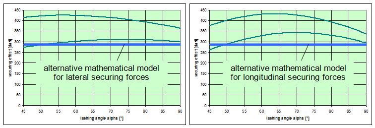 Figure 29: Alternative model for the securing effect (blue) 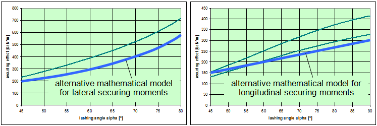 Figure 30: Alternative models for the securing effect (blue) The blue curves in Figures 29 and 30 represent the securing effects in accordance with the proposed simplified models given in Equations (48) through (50). The green curves show the actual securing effects from Figures 18, 20, 22 and 24. At this point, it is important to note that the proposed simplification of the mathematical models is entirely independent of the open question as to which coefficient of friction is to be used in Equation (48). This issue must be dealt with separately. This does not, however, resolve the shortcoming in the conventional mathematical models described in Section 1.2, namely that the horizontal components of the tie-down lashing that arise as a result of friction between the belt and the cargo are ignored, which means that the existing dominance of the coefficient of friction μL or the resting moment lever b is further exaggerated. This minor shortcoming could be resolved by employing a small, fixed proportion of the standard tension force STF. The securing effect against lateral and longitudinal sliding could then be as follows, for instance:
However, it seems that the expense of more complex formulae is not worthwhile for the sake of a cosmetic change such as this. Top of page 1.5.2 Coefficient of friction between the loading surface and the cargoThe crucial question of what coefficient of friction between the cargo and the loading surface to use in a mathematical model for tie-down lashings cannot be answered on the basis of the considerations and calculations offered in Section 1.4. The choice is between a value that approximates to the coefficient of static friction, as proposed by the DIN EN 12195-1:2011 standard, and the coefficient of dynamic friction, as required by the predecessor standard DIN EN 12195-1:2004 and the VDI 2700, Part 2 Guideline. This decision affects both the actual securing effect and the securing effect determined on the basis of simplified mathematical models to much the same extent. As a fundamental principle, careful long-term analysis of claims and accidents should form the basis for an economically viable decision in this respect. However, as long as not even the minimum requirements for an adequate tie-down lashing appear to have been met in the majority of registered cases, it is difficult to draw the correct conclusions from experience to date. This decision has a serious impact due to the non-linear nature of the effect of the coefficient of friction on the number of belts that need to be employed (cf. Figure 3). This has been described in Section 1.2. The arguments on both sides that have been voiced to date are as follows:
The reference to practical trials in the first argument reflects a holistic approach. It includes the actual circumstances surrounding an event in which a cargo is subjected to a load. These include all positive and negative influences, such as small vertical accelerations, small additional dynamic loads as a result of movement of the cargo and the entire securing effect of the tie-down lashing as described in Section 1.4. The second argument refers to the simplified mathematical models and can even claim that the actual securing effect will generally even be somewhat larger than indicated by the models. On the other hand, part of this gain is „used up“ by the fact that, at least in the model proposed in DIN EN 12195-1:2011, the coefficient of transmission k is not fully accounted for and must therefore be compensated for by additional effects, as indeed it is. It is, however, undoubtedly the case that the second argument fails to take account of the circumstances surrounding a real load scenario, i.e. vertical accelerations and dynamic effects. The following considerations can also be raised independently of the arguments discussed:
In 2004, the discussions that followed the publication of the EN 12195-1:2003 standard led to a series of practical trials being carried out in Sweden. These were intended to clarify a number of contentious issues. One of these issues was the question of what coefficient of friction to use when dimensioning tie-down lashings. This involved six practical trials with emergency braking. The longitudinal and vertical accelerations were recorded. The cargo, which was secured with tie-down lashings, was a roll of paper, weighing 600 kg and standing on end. The coefficient of static friction between the roll of paper and the loading surface had previously been determined to be 0.54 on the basis of three pulling tests. The tie-down lashing was made up of one polyester belt attached crosswise across the vehicle with a lashing angle on both sides of α = 58.7°. For each of the six trials, the pre-tensioning force for the tie-down lashing was gradually reduced.
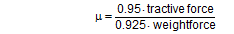
Using the coefficient of dynamic friction, the tie-down lashing that was the subject of the trial would have required a pre-tensioning force of approximately 600 daN (as the sum of both sides). Using the coefficient of static friction, however, it would have required only approximately 250 daN. As expected, the series of trials showed that the cargo only starts sliding when the necessary securing force is greater than the friction that can be provided by the coefficient of static friction. This was the case in the sixth trial where the coefficient of static friction of 0.54 was exceeded. In the fifth trial, the slight increase in the pre-tensioning force indicates that the roll of paper was just about to move. After the static friction had been overcome in the sixth trial, the roll of paper began to move forward. At this point, the forward-acting inertial force becomes greater than the lower dynamic friction that now applies, triggering an acceleration of the roll of paper. This movement is, however, quickly inhibited because the belt is forced to stretch, thus increasing its tension. In addition, the displacement of the roll causes a small, rearward and directly acting force component. This is caused by the additional securing effects of the tie-down lashing described for longitudinal sliding in Section 1.4.5 of this paper. Although it is hardly surprising, this series of trials and its results clearly demonstrate the dilemma inherent in this problem. If the tie-down lashing is dimensioned on the basis of the coefficient of dynamic friction, it can be assumed with a considerable degree of certainty that the cargo will never slide in the event of it being subjected to the defined reference load. However, securing the cargo in this case involves a considerable amount of effort due to the non-linear nature of the influence of friction, as has been mentioned several times, and this effort would in effect be wasted, because this amount of securing would never actually be called upon. In economic terms, this is a dubious approach. If, on the other hand, the tie-down lashing is dimensioned on the basis of the coefficient of static friction, it is, for several reasons, possible that the lashing will not quite be adequate and the cargo will begin to move as a result of the lower coefficient of dynamic friction. Although the additional securing effect of the tie-down lashing described in Section 1.4 will generally be able to restrain the cargo, this is not certain. We should also not forget that some of this additional effect is intended to compensate for other deficits of the simplified mathematical models. The conclusion drawn in the Verify-Report(6) states that the vertical accelerations that occur under emergency braking do not have any significant impact and therefore the use of the coefficient of static friction when dimensioning a tie-down lashing is „correct in physical terms“. This conclusion cannot be accepted without reservations. It is too biased in the context of the considerations listed above. Not only that, the small number of trials and the fact that the experiment was conducted only on a particular type of vehicle and a single type of cargo mean that the trials were not sufficient to draw such a general conclusion. A solomonic solution that should satisfy everybody could be as follows: The mathematical model should use a gradually reduced coefficient of static friction which would require that a somewhat larger number of belts or greater pre-tensioning forces would need to be used than with the actual coefficient of static friction. In this way it would be possible to reduce the probability that the actual coefficient of static friction is insufficient to an absolute minimum, which would be accepted by everyone. It is conceivable that the definition of the coefficient of friction to be used for tie-down lashings as laid down in Annex B of the DIN EN 12195-1:2011 standard is very close to this solution. This standard specifies the use of a standard value μ that can be empirically determined in two different ways:
The standardized equality of these two results and their relationships to static friction and dynamic friction permit a conclusion regarding the assumed relationship between dynamic frictionμD and static friction μS. Of course, any such relationship can only be understood as an approximate reference value, because, as is known, no physical regularity applies here.
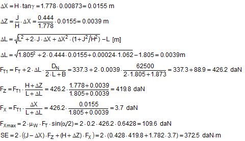
Anticipating Chapter 2, we should mention here that, when taking account of friction with a direct lashing according to DIN EN 12195-1:2011, the standard coefficient of friction μ as defined above should be reduced by a factor of fμ = 0.75. A coefficient of friction of 0.75 × 0.925 × μS = 0.694 × μS is thus proposed for evaluating a direct lashing. A study completed in Germany in 2007(8) entitled „Investigation of the effectiveness of frictional forces when securing loaded goods for transportation“ came to entirely different conclusions and recommendations. The study contains the results of pulling tests using anti-slip materials and pulling tests with and without tie-down lashings under quasi-stationary conditions and under the influence of vertical vibrations of the loading surface. The tests with and without tie-down lashings are important in the current context. 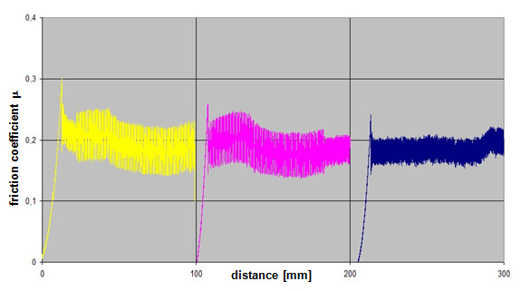 Figure 31: Coefficients of friction during pulling tests without tie-down lashings (source: Flog) Figure 31 shows the coefficients of friction derived from the ratio between tractive force and weight force from a series of three trials using the material pair of structured screen-printed laminate deck and rough-sawn Euro pallet. In the first trial, the coefficient of static friction is 0.3, and then falls to 0.26 and 0.24. The mean coefficient of dynamic friction is 0.18. These values are remarkably low compared with other specifications for the same pair of materials that have been under discussion. DIN EN 12195-1:2004: μS = 0.5 μD = 0.35 DIN EN 12195-1:2011: μS = 0.4865 μD = 0.4164 (converted from standard μ) In a reference test, the same cargo unit weighing 400 daN was secured with two tie-down lashings with lashing angles of α = 80° on both sides and a pre-tensioning force of around 350 daN on both sides. This cargo unit was then pulled. Note: This tie-down lashing was dimensioned in such a way that it should have been able to withstand a tractive force corresponding to a deceleration of 0.8 g without sliding, assuming a coefficient of friction of 0.18. This is shown in the following balance calculation:
The coefficient of friction of 0.18 that was assumed approximately corresponds to the mean coefficient of dynamic friction from the previous trial. Using the coefficient of static friction of approximately 0.30 determined in that trial, the cargo unit should only have started to slide at a tractive force of 484 daN. This would correspond to a deceleration of 1.21 g. In fact, however, in the first trial the cargo unit began to slip at a tractive force of less than 200 daN, i.e. at half its own weight, as shown by the chart in Figure 32. 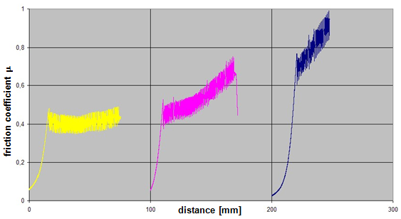 Figure 32: Coefficients of friction during pulling tests with tie-down lashings (source: Flog) The fact that the coefficients of friction appear to increase in the second and third trials is the result of elastic stretch and the increase of force of the belts and of their longitudinal component, which acts directly. These increase the tractive force applied during the trials and hence the apparent coefficient of friction. The University of Dortmund study puts the surprisingly large shortfall in securing effect down to possible settling effects and plastic stretch of the lashing belts along with other influences. This does not, however, appear particularly plausible. If we assume the same coefficient of static friction μS = 0.3 as in the first trial without tie-down lashings, the effective mean pre-tensioning force FT in the tie-down lashings when the cargo begins to slide can be calculated to give a tractive force of 0.48 times the weight. The balance calculation reads:
It is not particularly likely that the pre-tensioning force fell so dramatically from around 350 daN to around 60 daN as a result of settling effects or plastic stretch of the belts. Despite this open question, or perhaps precisely because the issue could not be resolved, the authors of the study concluded that „the coefficient of dynamic friction should be used rather than the coefficient of static friction when calculating cargo securing measures. The experiments conducted have shown that this requirement should be regarded as an absolute minimum which must be observed.“ This recommendation was made in 2007, but clearly carried no weight during the consultation phase leading up to the new version of EN 12195-1 between 2008 and 2010, with the consequence that the mean value between the static and dynamic coefficients of friction was to be taken as the standard. On the other hand, this study had a lasting impact on the VDI 2700 Part 14 Guideline published in September 2011 under the title „Determination of coefficients of friction“. This guideline defines a safety factor S = 0.95 by which the coefficient of dynamic friction established with pulling tests is to be multiplied before it can be used to assess cargo-securing measures. To the surprise of some European delegations, this safety factor then appears in EN 12195-1:2010 and DIN EN 12195-1:2011 (see Equation (53) above). |
|||||||||||||||||||||||||||||||||||||||||||||||||||||||||||||||||||||||||||||||||||||||||||||||||||||||||||||||||||||||||||||||||||||||||||||||||||||||||||||||||||||||||||||||||||||||||||||||||||||||||||||||||||||||||||||||||||||||||||||||||||||||||||


|
Top of page
| Contents
| |