
| Photo of the month – September 2021 |
[German version] |
Freestanding concrete elements
This month, we have an interesting case to discuss: A lot had been done correctly, but, as so often, things were not taken to their logical conclusion, and much was also left undone.
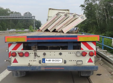
Figure 1 [Dortmund Police]
Figure 1 shows the result: Four concrete elements weighing a total of 18.1 tonnes have tipped to the right and are now hanging there in the tie-down lashings, some of which have become direct lashings, thanks to the changed geometry. It is very fortunate that nothing worse happened. The way that the loading bed has twisted is an indication of the tremendous forces at play here.
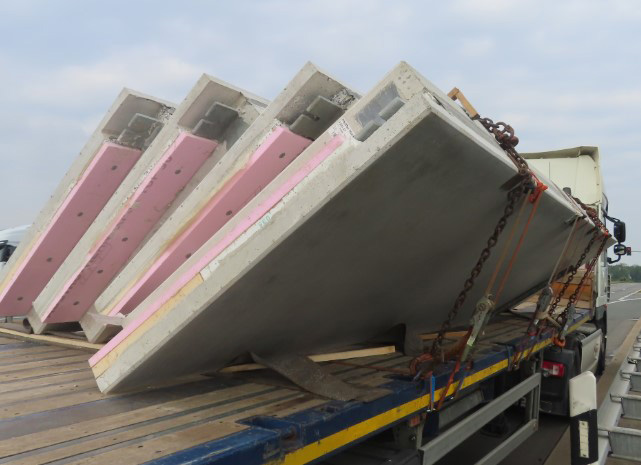
Figure 2 [Dortmund Police]
So what was done properly? Lumber and anti-slip material were used on the loading surface. In total, 10 pieces of load securing equipment were used, with three even being used as loop lashings, but sadly all with an effective restraining direction to the left. With so many items of load securing equipment, it would almost have been possible to secure the load well.
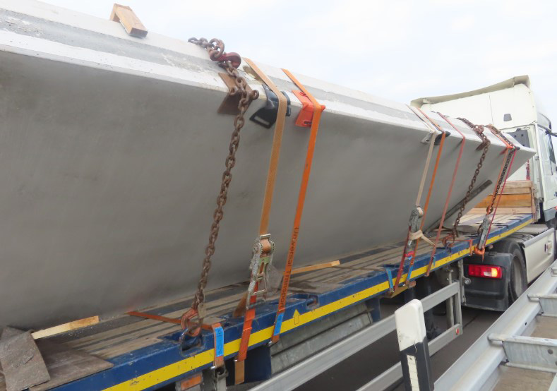
Figure 3 [Dortmund Police]
The fact that a mixture of different types of load securing equipment, namely belts and chains, was used is not really a problem, because most were used as tie-down lashings. In this case, the pre-tensioning force can simply be added together, although we would prefer to see only one type of equipment being used here.
Loop lashing:
A loop lashing is a type of direct securing, where the equipment used is able to provide its entire lashing capacity – 2000 daN per run for commonly used belts. The only drawback is that this securing effect only applies in one direction.
Example: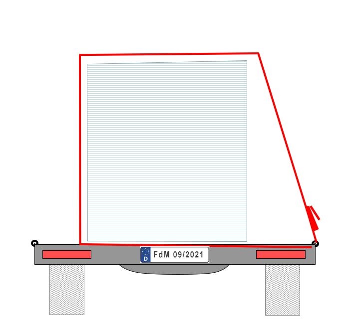
Diagram 1 [TIS]
Tie-down lashing:
The effect of a tie-down lashing is to artificially increase the weight of the load as a result of the pre-tensioning force, which in turn increases the friction between the load and the loading surface. This method of securing a load is often not the best choice for heavy loads and/or low levels of friction. The greatest advantage of tie-down lashings, occasionally referred to as “friction lashings”, is that their securing effect applies in all directions. In other words, to the front, to the sides and to the rear.
Example: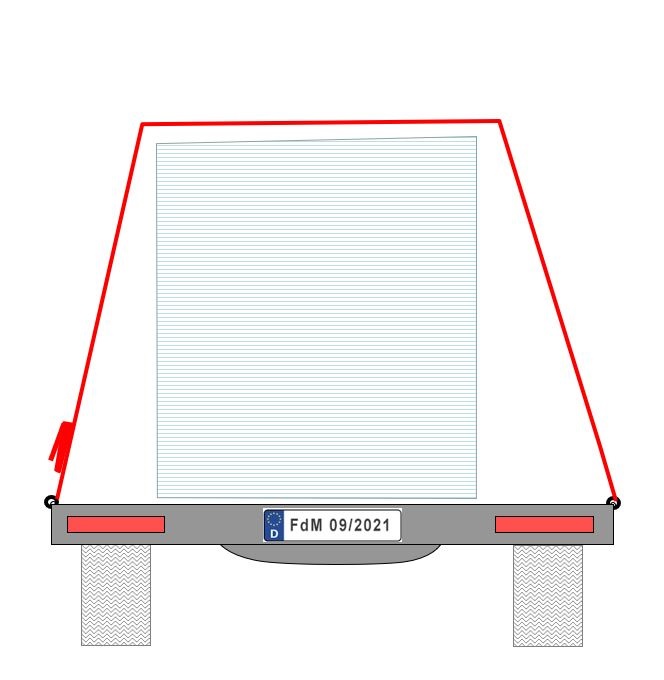
Diagram 2 [TIS]
To assess the way in which this load was secured, we carried out a calculation using the simplified Formula 17 as laid down in DIN EN 12 195-1. To do this, we only included the tie-down lashings in the calculation, not the loop lashings. If you want to see the calculation, visit this link.
This calculation showed that it was possible to secure a load with a mass of 7855.62 kg with these tie-down lashings.
The method of securing using tie-down lashings that was used here only provided a fraction of the necessary securing force. Although it is theoretically possible to secure the load with tie-down lashings, we believe that this method of securing would be extremely cost-ineffective. It is possible to secure the load in a way that is far superior to the one attempted here and that also requires a lot less effort. One striking thing about the way the driver secured the load is that he used three direct lashings (loop lashings) against movement to the left. Loop lashings such as these are precisely what we would recommend for such loads.
It remains a mystery why the driver did not use this securing method against movement to the right. Perhaps he overestimated the stanchion that was used at the front of the vehicle, which is sadly a common mistake. A stanchion such as this has a securing capacity of between 3000 daN and 4000 daN, but only just above the loading bed. This good securing capacity decreases rapidly with height. Since the concrete elements were leaning against the top of the stanchion, the stanchion had no chance of preventing tipping, because its securing effect was reduced to a few hundred daN at that height.
Important:
Stanchions such as those used here should be subject to loads in their lower portion, as close as possible to the loading area. As a rule, they are not suitable for securing a load against tipping. On a positive note, edge protection was used pretty consistently when securing this load. It was missing from only one belt.
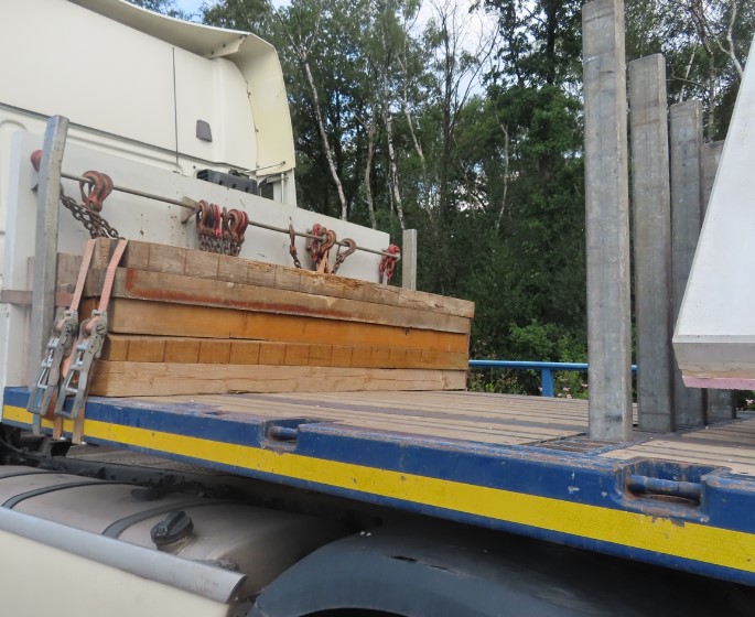
Figure 4 [Dortmund Police]
The way in which the load was secured to the front, on the other hand, left a lot to be desired. Assuming that the anti-slip materials were correctly placed underneath the load (above and below the lumber dunnage, so that the load was separated from the loading surface in terms of friction), the coefficient of friction μ of 0.6 would provide the lion’s share of the securing effect. This would mean that 0.2 x 18.1 t = 3620 daN of securing force would remain to be found.
Unfortunately, we were not told the nominal pre-tensioning forces of the lashing equipment. We shall therefore assume an STF of 350 daN and generously double this for the tie-down lashings (seven in number) to obtain 4900 daN of pretensioning force. The angles are good, so we shall not make any deduction. This results in the following calculation: 4900 daN x 0.6 = 2940 daN of securing force. There is now a shortfall of 680 daN of securing force to the front. It could be that the chains had considerably more pre-tensioning force than we assumed. If this was the case, then the securing force to the front would have been sufficient.
But that’s not the point of what we are saying. There were four stanchions in front of the concrete elements. And there was sufficient strong lumber stacked against the end wall. Instead of being stowed against the end wall, it could also have been placed against the stanchions to easily give the load a tight fit to the front. This would be a scenario that would play to the strengths of the stanchions. This is because their effect is greatest just above the loading bed and the stanchions also have a rectangular cross-section, which further enhances their longitudinal strength. We would calculate 4 x 3000 daN, which would be 12,000 daN for virtually no effort with this load scenario. It’s a pity that this securing option went unused.
The three loop lashings mentioned above were a good idea, but their counterparts are missing, and in fact they made matters worse by the fact that the pre-tensioning force of the loop lashings acts on the right-hand side of the vehicle, thus promoting a tendency for the load to tip to the right, which is what happened.
How to secure this load:
How would we secure this load?
Let’s start with preparation:
- Anti-slip material is attached to the entire top and bottom surfaces of heavy rectangular wooden dunnage.
- The concrete elements are then placed on this.
- If the elements are sensitive to contact with each other (chipped corners etc.), we also place cubes of squared lumber between the elements (see Sketch 3).
- On top of the elements, we place two wooden planks, on which cubes of squared lumber are nailed at the same positions as on the loading bed. The planks should not protrude beyond the load, as they will each be secured with a tie-down lashing.
- If the concrete elements are not susceptible to damage, they can also be loaded directly against each other.
- The direct lashings that are needed are laid out on the loading bed before loading.
- In the direction of travel, against the four stanchions, we place two stacks of three pieces of squared lumber to distribute the load on the stanchions.
Loading can now begin.
- The concrete elements are positioned one after another and the cubes of squared lumber are gradually nailed in place. Positioning the concrete elements is undoubtedly a challenge from the perspective of occupational safety.
- Once all the elements are in place, the planks with the cubes of squared lumber are inserted from above and are lashed down.
- To give the load more stability, we would attach two straps around the waist of the load to bundle the elements together to form a load unit, one towards the top and one towards the bottom. It would make sense to use anti-slip material to prevent these from slipping down.
- Now we come to the loop lashings. We assume that the load is liable to tip and must therefore secure it to the sides with a factor of 0.6. 18.1 t x 0.6 = 10,860 daN is the required securing force. We must ignore the anti-slip materials for this calculation, as they only serve to prevent slipping, not tipping.
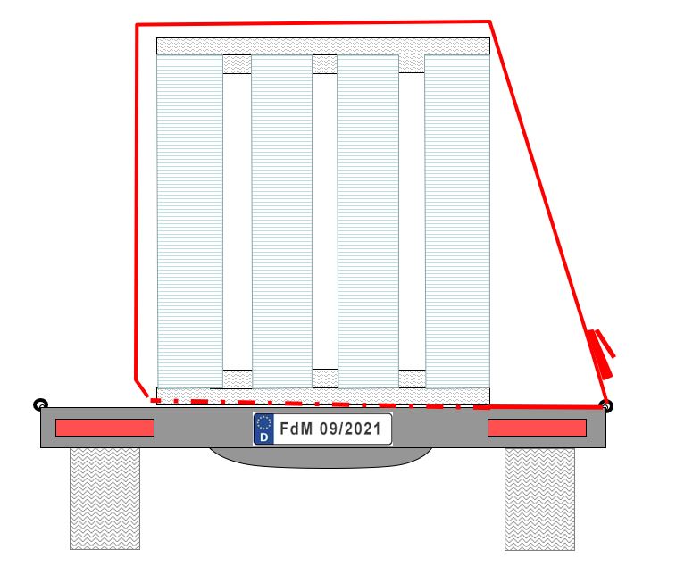
Diagram 3 [TIS]
Diagram 3 shows a loop lashing. To secure the load to the sides properly, each loop lashing must be provided with a counterpart acting in the opposite direction. Four of these lashings are required on each side.
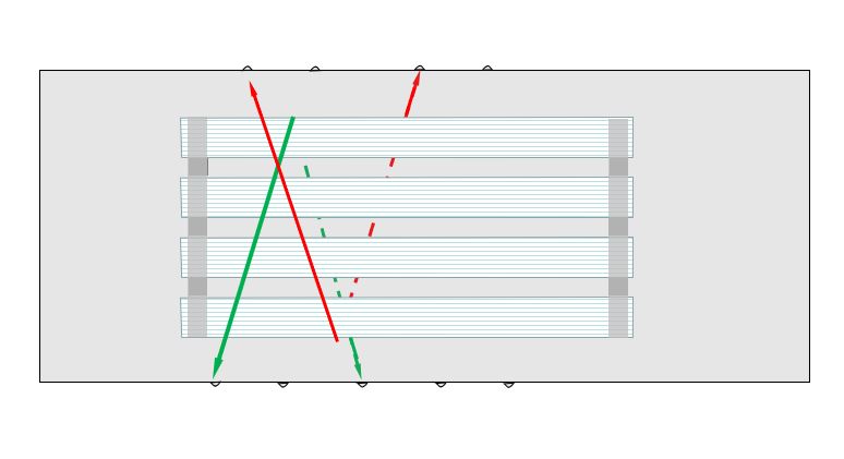
Diagram 4 [TIS]
This sketch shows the principle of loop lashings from above.
In the video below (in German only), we show you how to attach a loop lashing properly.
Video 1 [Wolfgang Jaspers]
Calculation:
The restraining force of loop lashings is calculated using cos alpha / 2. We assume a value of 80°. Alpha ½ results in 40° and the cosine of this is 0.77 (rounded up). A belt with an LC of 2000 daN used as a loop lashing provides 4000 daN (provided each end is attached to different load securing points). 4000 daN x 0.77 = 3080 daN of securing force.
10,860 / 3080 daN results in a value of 3.53. This means that we have to use four loop lashings per side to provide good securing of the concrete elements to the sides.
- These direct lashings counter the risk of tipping by combining the load into a single unit (opposing direct lashings).
- Edge protectors are, of course, the be-all and end-all. This also applies if chains are to be used as loop lashings, and a fine example of this can be seen in the photo.
- In total, therefore, we need eight belts for primary securing: two for the tie-down lashings for the planks with the cubes of squared lumber (if this securing method has been chosen) and the two belts around the waist of the load. So these concrete elements would be well secured with 12 belts or other securing mechanisms.
- To the front, we use the tight fit against the four stanchions on offer, but need another two tie-down lashings there to secure the squared lumber.
If we had the choice, we would transport these elements in a stable A-frame. After all, loading and unloading these elements with the loading arrangement above was rather bold, dangerous and undoubtedly time-consuming as well.
Your load securing columnists wish you a safe and secure end to the summer.
Back to beginning