
| Photo of the month – July 2014 |
[German version] |
Hand in hand?
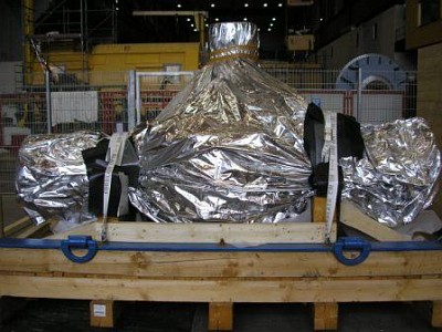
Packaging is one of our favorite topics in this column. The quality of the packaging is an integral aspect of safe transportation and hence goes hand-in-hand with issues of load securing. This double drop deck trailer is loaded with a 50-tonne overwidth and overlength crate.
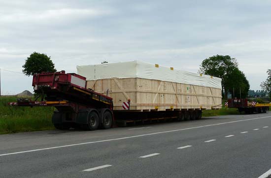
Figure 1 [Raymond Lausberg]
A tarpaulin on top of the crate protects it from rain, and there are a wealth of markings indicating how to handle it safely.
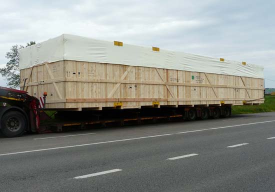
Figure 2 [Raymond Lausberg]
So far so good, we assume.
A glance at Figure 2, however, is enough to reveal that, as far as the securing of the load is concerned, there is no tight fit to the front. Furthermore, a trained eye will see that there only appears to be one belt passed over the back of the 50-tonne crate. And, below the crate, one would expect some kind of structure to allow it to be positioned on the double drop deck trailer.
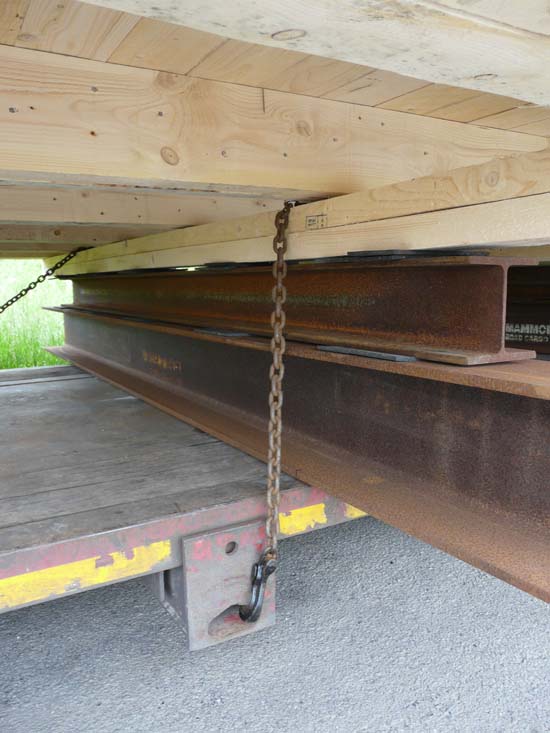
Figure 3 [Raymond Lausberg]
And so it is. Our expectations were entirely justified. Heavy I-beams of different heights have been used to compensate for the height of the rear platform. The I-beams even support the crate beyond the width of the vehicle and anti-slip mats have even been used to increase friction.
At this point, after so much praise, our regular readers will be expecting the first critical comments, and again, their expectations are justified. We shall have a careful look at all aspects of how this load was secured.
What method was used to secure the load?
Even for this 50-ton crate, a kind of tie-down lashing has been used. The total lack of load securing points on the crate forced the person responsible for loading it (probably the poor driver) to be creative. He passed a chain over the I-beams and one of the lateral members of the floor of the crate to the back of the vehicle to act as a sort of tie-down lashing. He intuitively attempted to secure both the unstable supporting structure and the crate simultaneously.
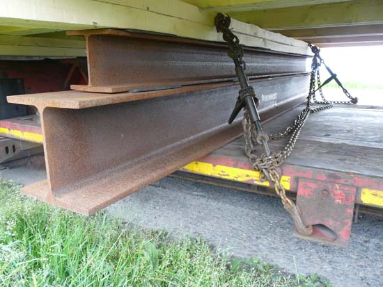
Figure 4 [Raymond Lausberg]
Let us spend a few moments more on the supporting structure. As we have already mentioned, anti-slip mats were used to increase the friction between the I-beams themselves and between the I-beams and the floor of the crate. And again, we have to say "so far so good". But why did the person who secured this load not consider all elements of the friction chain? How can the high level of friction between the floor of the crate and the I-beams, as well as between the I-beams themselves be passed to the loading surface when the friction-enhancing materials on this surface are conspicuous only by their absence.
Let us take a look at the tie-down lashings. These lashings are in fact a cross between tie-down lashings and direct lashings.
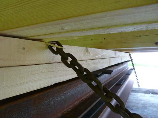
Figure 5 [Raymond Lausberg]
Figure 5 gives a good idea of how the chain is biting into the lateral member of the crate.
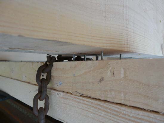
Figure 6 [Raymond Lausberg]
This can be seen very clearly in Figure 6. If this securing arrangement were to be subjected to any kind of load, the chain would necessarily slip over the squared lumber if the crate were to slide forwards. And in that sense, it is possible to refer to this as a "combined lashing".
Figure 5 has already shown that the chains follow different routes. The chain shown at the front of the picture is routed more appropriately for a direct lashing than the chain at the back of the picture. This is probably due to the fact that the load securing points are arranged differently. Not only that, Figures 3 and 4 show that the load securing points are not particularly suitable for the load securing equipment used, as some of the hooks are loaded in such a way that they will bend and, in at least one case, the load is not on the shoulder of the hook. And, without putting too fine a point on it, we are talking about securing a 50-tonne load.
The crate
Let us take a look at the star of this month's show, the crate and the way it is constructed. Figure 6 speaks volumes. The poor person responsible for securing the load made the best of a bad job by passing the chains over a lateral beam under the crate. At this point, this lateral beam is secured to one of the main longitudinal wooden members of the crate with the seven nails that can be seen. Because the crate was apparently not resting flat on the supporting structure, the tie-down lashing was able to pull the lateral beam away from the floor of the crate by a small amount. To be fair, we should say that this combined tie-down/direct lashing is merely an expression of the overwhelming sense of helplessness that must have been experienced by someone attempting to do the impossible, namely to secure this crate properly.
Transport insurers use the term "fit for purpose" to describe adequate packaging. All this means is that packaging must be able to withstand the loads experienced when it is used for its intended purpose. This crate appears to have been built to be handled using cranes, but those who constructed it clearly completely forgot to take transport by road into account.
Possible solutions
If the crate is going to be transported on a double drop deck trailer anyway, one could consider making use of a tight fit to the front gooseneck. If this is not possible or if the construction of the crate does not fully permit this, then the crate must be fitted with appropriate load securing points. If the load cannot be secured adequately, it is not possible to transport this crate and, as can be seen in the picture, the Belgian police put an end to the journey here.
The pictures below show examples of sensible load securing points.
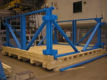
The figure SVT 6 shows a thoroughly stable crate with load securing points that protrude externally. These load securing points are bolted to the frame of the crate in several places with a steel plate. They need to be able to withstand the loads that are to be expected on the road and at sea (fit for purpose). If the cargo is transported by road, the externally accessible load securing points would, in our example, need to be able to withstand a total load of at least 50 tonnes or the forces required to secure such a load.
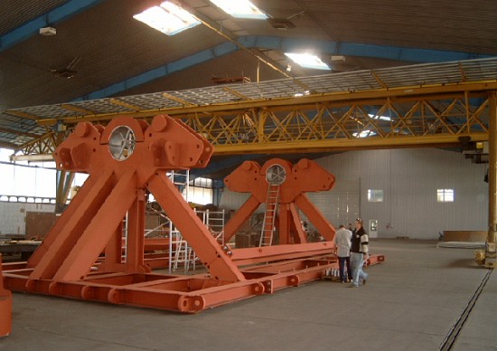
The figure SVT 7 shows a steel cradle that is also equipped with load securing points all round that will withstand the expected loads and allow the extremely heavy cargo to be secured properly.
The figure SVT 8 also shows a crate made of different materials (lumber for the floor of the crate and a solid steel frame at the sides). Here also, load securing points have been fitted in such a way that they can subsequently be accessed easily from the outside of the crate. This is a basic requirement for safe transportation. When dimensioning the load securing points, it is necessary to consider not only the distance the cargo is to be transported, but also the manner in which the crate will be carried. The supporting structure shown in our example will only transmit any friction in a lateral direction. In a longitudinal direction, we have to assume that the structure will at least tilt. Because this structure means that friction will only be transmitted to the vehicle in a longitudinal direction via the rear gooseneck, and this is the only way in which the load is secured, the load securing points should be dimensioned in such a way that they are able to restrain the weight of at least the entire crate. With overwidth loads, the routing of the load securing equipment can in itself be a significant problem. In the case of this cargo, it may even make sense to locate load securing points under the cargo. Depending on whether the longitudinal members of the crate can cope with being weakened by being drilled, a viable alternative to load securing points would be to drill holes in these members. Of course, these holes would need to be protected from the chains or other load securing equipment using tubes and side plates to ensure that the forces are transmitted to the longitudinal members rather than permitting the members to be damaged by the load securing equipment.
Summary
In closing, we want to repeat the title of this Photo of the Month: Packaging and load securing go hand-in-hand. Anyone who wants their cargo to be transported safely (and all those involved are obliged to do so) has to construct the packaging in such a way that the cargo can be secured appropriately on any form of transport.
We wish you a safe journey.
Your Load Securing Team
Back to beginning