
| Photo of the month – February 2014 |
[German version] |
Zig-zag lashing
It is not always as easy to find a suitable title for our articles as it is this month. The photo below made life easy for us!
Whoever secured this load appears to have threaded the belt on a zig-zag route through the load. It would appear that he thought that the reels of wire on the spools were definitely liable to drift apart. He therefore attempted to join as many as possible of these frames together while exerting the least possible pressure and using as few belts as possible. And it seems that he actually succeeded to a certain extent, insofar as the belts are tensioned a little and somehow exert forces between the individual frames.
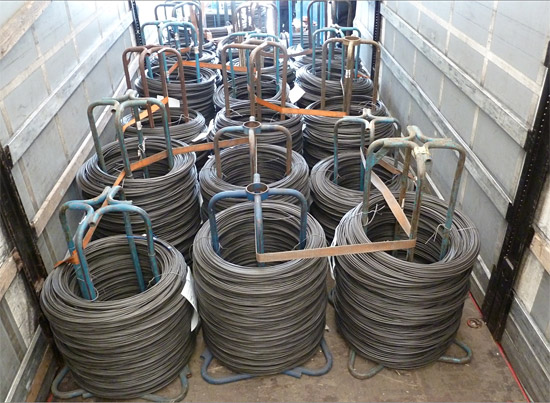
Figure 1 [Gerhard Howanietz]
But in reality this zig-zag lashing has very little to do with proper load securing.
Figure 2 gives some idea of the challenges faced by anyone attempting to secure this load:
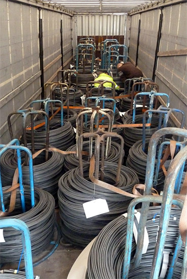
Figure 2 [Gerhard Howanietz]
In our role as load-securing columnists, we are grateful for pictures such as these. After all, we rarely find a picture that yields so many issues to discuss as this one does.
The frontmost 6 or 8 spools have not been loaded as a tight fit against the end wall. They are somewhat larger than those loaded further behind and there is a considerable gap between them and the rear load "block". In this gap, we can see the driver and the police officer who is carrying out the inspection discussing some of the issues about the way in which the load has been secured in situ. It is almost certain that the load was arranged in this way in order to meet the requirements of the load distribution plan. It is, of course, a positive sign when those responsible for securing cargo spare a thought for the way in which the load is distributed. These spools present a number of challenges:
- They have an irregular shape. Some have a round base, while the base of the others is more square and pushed in at the sides.
- The spools are of different sizes. At the front, they can only be loaded two abreast, and at the rear three abreast.
- No tight fit can be achieved between the tops of the spools. If it is possible to achieve a tight fit at all, it is often the case that the wire coils are touching each other or the base of the spool is in contact with the neighboring spool. But this is insufficient to achieve a compact, tight-fit block.
- The different amounts of cargo on the various spools means that the load units no longer have a uniform size. This means that they no longer fit onto the vehicle in such a way that they occupy the entire width of the vehicle as a tight fit when loaded two abreast. This means that it is not possible to make use of a tight fit to the sides.
Figure 3 shows the gap between the front and rear load blocks. The last two spools of the front load block are in fact four, because spools have been stacked on top of each other. The paper, cardboard or plastic that has been placed between the individual frames indicates that this is sensitive cargo:
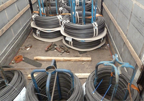
Figure 3 [Gerhard Howanietz]
Before we go into further detail about the way the load was secured, we want to have a look at the load units. These load units are associated with a whole raft of problems. Neither at the base of the load unit nor at the top is it possible to achieve a tight fit that can be exploited for securing the load. We need not repeat that the zig-zag lashing delivers no load-securing effect, but it does show the perplexity of the person who tried to secure the load. It is probable that he was not permitted to simply lash down the sensitive wire coils. It is also probable that it would not even have been possible to lash these wire coils down effectively, because the vibrations from the vehicle would have caused them to settle within a few hundred meters, and any pre-tensioning force in the belts would have been lost. Not only that, the tops of the spools themselves are so rounded that any attempt to lash down the load using the spools would have failed miserably.
So how could load units such as these be improved?
Clearly, these spools are used very frequently, so a certain amount of effort is justified. Once again, the watchword is modularity. Modularity means that the load unit itself or multiple load units can be loaded as a tight fit on a truck from side to side or from front to back. This has the considerable advantage that this tight fit to the sides, and possibly to the front, can be exploited when it is present. In the case of these frames, this would mean that the bases of the spools could be secured to a metal frame similar to a pallet. These pallets should be dimensioned in such a way that either two or three completely occupy the available loading width as a tight fit. This approach would ensure that a good tight fit could be achieved at the base of the spools. If the tops of the spools were also designed in such a way as to allow load-securing belts to be placed on top of them, preferably in two directions, it would then also be possible to lash down the spools without any difficulty. This would only apply if the spools themselves were loaded, otherwise the tie-down lashing would tip them towards each other. Even if three spools were loaded abreast, it would be no problem to lash all three down effectively with a single tie-down lashing, provided that there was a tight fit to the front. Of course, we assume that appropriate anti-slip material is used if the load is secured in this way. The use of anti-slip material delivers a coefficient of friction µ of 0.6. To achieve a coefficient of friction µ of 0.8, an additional 0.2 x the weight force of the load must be applied, and this can be done with a tie-down lashing.
This tie-down lashing method (Diagram 1) assumes that the spools are secured firmly to the pallets (e.g. by bolting) and that the wire coils are not sensitive to pressure, because the belts pass over the sides of the coils:
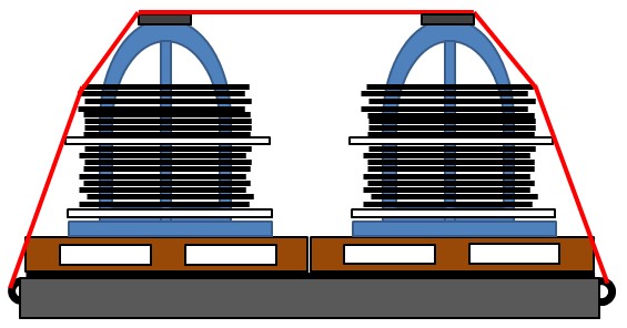
Diagram 1 [GDV]
If the wire coils are sensitive to pressure, an appropriately dimensioned U-shaped bar can be placed on top of the spools, and the belt can be passed over the resulting channel, for instance. The bar should have appropriate recesses where it passes over the tops of the spools to prevent it from slipping:
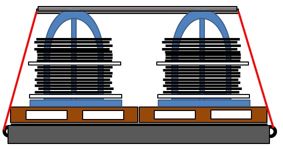
Diagram 2 [GDV]
Figure 4 clearly shows the difficulties of achieving a tight fit with these load units. None of the load units shown comes anywhere near exploiting the tight fit potentially available against the strong side walls. The varying shapes of the load units make this virtually impossible:
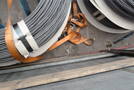
Figure 4 [Gerhard Howanietz]
Figure 5 shows an extremely loose tie-down lashing that has slipped. This load unit is made up of two stacked spools on which at least the top wire coils are bound reasonably tightly with steel straps. Clearly, it was either the flexibility of the load itself or the irregular shape of the load units that caused this tie-down lashing to become completely ineffective:
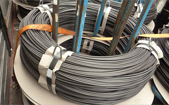
Figure 5 [Gerhard Howanietz]
Figure 6 shows the first two load units, which have not been loaded as a tight fit against at the end wall. Again, these have been stacked, and are made up of large spools, and an attempt was made to lash them down with a tie-down lashing:
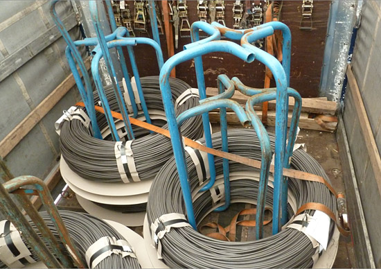
Figure 6 [Gerhard Howanietz]
With a certain amount of goodwill, we could possibly assume that this tie-down lashing actually delivers some securing effect. On the other hand, it is possible that the belt is pushing the load unit forwards a little; but we do not wish to be too pernickety. We note with interest that the photographs shows some 15 or 16 tensioning devices hanging on the end wall alone. Some have short and some long tensioning handles. Which means that this vehicle appears to be excellently equipped with load-securing equipment. And with this photograph, we should also like to draw attention to the fact that an attempt was made to place anti-slip mats under the load units, at least in part.
In Figures 7, 8 and 9, we shall have a close look at the loading surface. Figure 7 clearly shows that the loading surface has already been subject to a considerable amount of wear and tear:
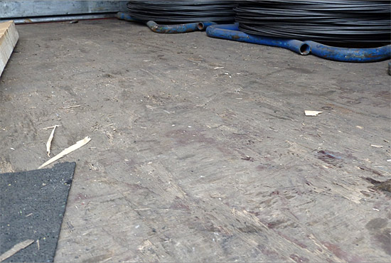
Figure 7 [Gerhard Howanietz]
We have to assume that this loading surface is no longer completely flat. Indeed, it is likely to have differences in height of several millimeters. This photograph also shows that the load units are standing directly on the loading surface without any anti-slip mats. We can also see the quality of the anti-slip mats the vehicle is equipped with. We shall come back to the condition of the anti-slip mats. But one important fact is that the anti-slip mat shown in Figure 7 is 2 or 3 mm thick at most. How can such a thin anti-slip mat be expected to provide a friction bond between the load units and the loading surface when the loading surface itself is in such a poor state? This would appear to be impossible.
Figure 8 gives us more cause to talk about friction. What level of friction can we assume here? The load unit is standing on a steel beam that has been smoothed through use. This means that we can only assume a coefficient of friction of 0.1 or 0.2:
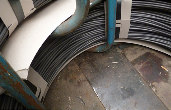
Figure 8 [Gerhard Howanietz]
And Figure 9 completes our collection of friction curios. The load unit is partly standing on a steel beam, partly on the loading surface and, perhaps, to a small extent on the anti-slip mat, which is far too thin in the first place. In this case, the anti-slip mats are not even merely decorative. It appears as if they simply happened to be lying around on the loading surface and that the load units were loaded randomly without any consideration for the position of the mats:
Figure 9 [Gerhard Howanietz]
In Figure 10, attentive readers will see something that has probably already been troubling them in the previous three pictures. The loading surface is far from clean. Indeed, it is so dirty that even the anti-slip mat is affected. The anti-slip mat shows considerable signs of wear and tear and, as already mentioned above, it is far too thin to raise the load from the loading surface in order to achieve a good level of friction. Furthermore, this anti-slip mat has already been subjected to excessive loads at the points indicated. This may have been caused by other cargo, but it is certainly possible that it could have resulted from the spools, because the tubes only touch the anti-slip mat along particular lines and can exert a considerable amount of pressure. This can cause the anti-slip mat to disintegrate into a mass of crumbs and become counterproductive, as if the surface had become a sea of marbles:
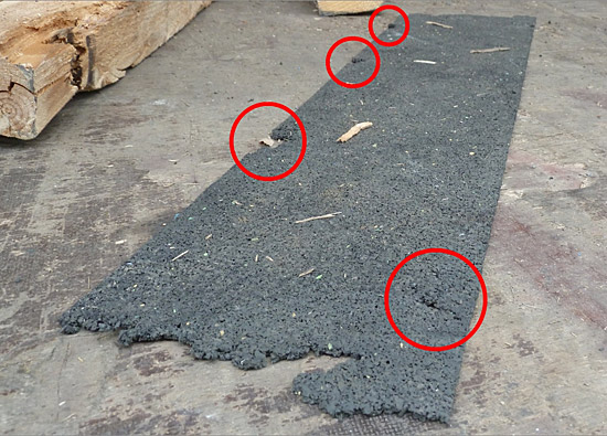
Figure 10 [Gerhard Howanietz]
Note:
Anti-slip mats must always be able to lift load units from the loading surface to achieve better friction. This means that they must be thick enough to ensure that no part of the load touches the loading surface and that all parts of the load are in contact with the anti-slip mat. Given the rigors of loads such as this, it is also advisable to use heavy-duty mats with a thickness between 8 and 12 mm. Only in this way is it possible to realize the positive effects offered by the use of anti-slip material.
What particulary interests us in this picture are the removable slats. The bottom two are made from aluminum and the top one from wood:
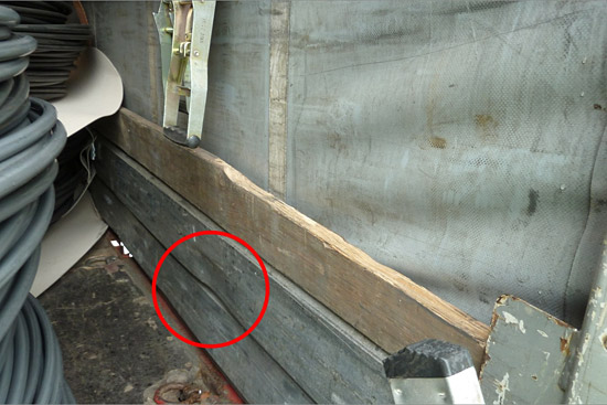
Figure 11 [Gerhard Howanietz]
Depending on the quality and design, these removable slats are able to provide a boundary to the loading area that is capable of withstanding loads. If this is to be done, the shaped bottom aluminum slat must be able to rest as a tight fit in the vehicle frame or on the loading surface. This tight fit must in turn be passed from aluminum slat to aluminum slat. An aluminum slat that has buckled is indicated in the picture. Damage such as this regularly occurs when the vehicle has been uncovered and the aluminum slats have not been pushed far enough under the vehicle, so that a forklift truck can drive onto or over them. Because the thickness of these removable slats is a considerable factor in respect of their strength, the logical conclusion is that they are useless if they have been flattened. The topmost wooden slat has already fractured at the end, so that it would be better used as firewood. In any event, wooden slats such as this cannot be used to construct a boundary to the loading area that is capable of withstanding a load, unlike removable aluminum slats that have been specially shaped.
Note:
In this case, no accident occurred. Perhaps the driver was lucky to be stopped by the police for a routine inspection. In this way it was possible to explain to him, but also to the owner and person responsible for loading, that this attempt to secure the load was entirely inadequate.
Often, it is enough for the driver to swerve to cause the load to fall from the bed. Our Photo of the Month from April 2007 is enough to show that we are not just imagining this. In that case, the load dropped onto the motorway.
Your load securing columnists wish you all a safe journey every time!
Back to beginning