
2 Direct securing |
[German version] |
|
When securing cargoes to a vehicle, the term „direct securing“ refers to all methods whose primary mode of action makes use of „positive locking“ force transmission between the cargo and the vehicle. This is the key difference compared with friction securing (tie-down lashing), whose primary mode of action is a „non-positive“ or „frictional“ connection between the cargo and the vehicle, which is merely increased somewhat by the tie-down lashing. Whereas the effect of force transmission through positive-locked connections is limited by the strength of the material used for securing, friction is subject to greater restrictions, which are only marginally influenced by the material used for securing. This means that direct securing can be more efficient than friction securing using similar materials by something in the region of the power of ten. Example: A belt used for a direct lashing can be loaded up to its lashing capacity LC of, e.g. 2500 daN. If the same belt is used as a tie-down lashing and is tensioned with the standard tension force STF of 400 daN, and if a coefficient of friction μ = 0.3 is taken, it provides a maximum securing effect of 2 × 0.3 × 400 = 240 daN. If a belt is used to secure a cargo directly and is attached at an angle that differs from the required securing direction, its effectiveness is reduced. The mathematical models in the guidelines and standards discussed account for this in a reasonably uniform manner. However, none of the specifications take mathematical account of the fact that the potential securing effect is only achieved after the cargo moves noticeably. If the lashing angles are unfavourable, such movement can be of a dangerous magnitude. Only in the DIN EN 12195-1:2011 standard is the necessary movement of the cargo mentioned, with the consequent requirement that the coefficient of dynamic friction should be reduced by 25% before it is used in the force balance calculations for the longitudinal and lateral directions. This can be understood to be the coefficient of dynamic friction. The fact that the effectiveness of direct securing depends on movement of the cargo also has a further consequence, namely that combinations of securing equipment that act directly can only act with their full lashing capacity LC if they have the same elastic properties relative to the direction in which the cargo moves. These restrictions surrounding the use of direct lashings will be explained in more detail with examples in the sections below. Top of page2.1 Necessary movement of the cargoAccording to Hooke’s law, all solid bodies, which includes cargo-securing equipment, must deform when they transmit a force. For lashing equipment, this deformation will take the form of stretching, and for blocking equipment, it will take the form of compression. If such deformation remains within the permitted range, it will be elastic. In other words, the deformation is not permanent, and the force transmission process can be repeated any number of times. And this is precisely what we expect of cargo-securing equipment. Hooke’s law further states that for practical applications in the lower load range, the load absorbed and the associated deformation are proportional to each other. This simplifies all calculations. This assumption fits very well for metallic lashing materials and rather less so for synthetic fibre belts, although it is still adequate here (see Figure 17). This assumption can also be made for timber used for blocking if it is subjected to loads over brief periods. The concept of the elastic constant as introduced in Section 1.4.3 is used to determine the movement of the cargo necessary to transmit forces on the basis of Hooke’s law. The elastic constant D permits simple conversion of a change in length ΔL to a change in force ΔF and vice versa as shown in Equation (26):
and in accordance with Equation (28):
Assuming 4% elastic stretch for lashing belts and 1.5% elastic stretch for chains, this allows us to derive the following values for the nominal elastic constants in daN when the LC is reached:
Top of page 2.1.1 Lashing devicesLashing devices for direct securing are attached between a securing point on the cargo unit and a securing point on the vehicle. Depending on the precise circumstances, the direction of the lashing device will deviate from the ideal, which should be aligned with the direction of the force to be transmitted. The resulting lashing geometry has a considerable impact on the movement of the cargo that is required to transmit the forces. Figure 33 shows a lashing of the length L running at a vertical angle α to the loading surface. The horizontal angle of the lashing also deviates from the longitudinal axis of the vehicle by an angle of βx. The concomitant deviation from the lateral axis of the vehicle is represented by the horizontal angle βy. Equally well as by the description above based on angles, the lashing geometry can be described by the geometrical components of the lashing X, Y and Z. This option makes the formulae somewhat clearer and will be preferred below. 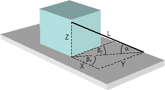 Figure 33: Geometry of a direct lashing The three-dimensional version of Pythagoras‘ theorem applies to the above-mentioned components X, Y and Z and the length L of the lashing (where L is the internal diagonal of a cuboid with the sides X, Y, Z):
The lashing is defined as having a pre-tensioning force of FT. In order to reach the lashing capacity LC, it must stretch by the distance ΔL. The following applies:
Sliding movement of the cargo If a load is applied in the direction x, the cargo unit must move by the distance ΔX in order to cause the change in length ΔL. Applying Pythagoras‘ theorem:
If a load is applied in the direction y, the cargo unit must move by the distance ΔY.
Equation (55) shows that the change in length ΔL can be kept to a low value for a given lashing capacity LC by applying a high pre-tensioning force FT, by keeping the length of the lashing L as short as possible, and/or by using a material with a large nominal elastic constant, such as a steel chain instead of a synthetic fibre belt. Equations (56) and (57) can be reformulated in such a way that it is possible to estimate the relationship between the movement of the cargo and the change in length. These reformulations are as follows:
If we consider that the two added values are small compared with twice the base values, the following provides sufficient accuracy:
The movements of the cargo are therefore virtually always greater than the changes in length, and never smaller. They can only be restricted by the magnitude of the changes in length if the lashing is only arranged in the x direction or y direction, i.e. if it has no other components. However, if X or Y is close to or equal to zero, which should anyway be regarded as an extremely inefficient arrangement, the approximations (59) provide incorrect results, which are too large. Calculation of ΔX and ΔY using Equations (56) and (57) should therefore always be preferred. Example: We shall calculate a simple example in order to demonstrate the sort of magnitude we are dealing with. A lashing is attached in a manner similar to that shown in Figure 33, with the following length components: X = 1.4 m, Y = 2.0 m, Z = 1.3 m. The length of the lashing is thus:
The lashing is a single lashing belt with an LC of 2500 daN. It has been pre-tensioned to STF = 400 daN. The change in length necessary to reach the LC is:
If a load is applied in the x direction, the necessary movement of the cargo as per Equation (56) is:
If a load is applied in the y direction, the necessary movement of the cargo as per Equation (57) is:
Neither of these results is extreme, but nevertheless demonstrate that a considerable movement of the cargo can be necessary if it is secured directly using belts. Tipping movement of the cargo A cargo unit that is liable to tip rather than slide must tilt by a small angle Δδ in order to generate the elastic stretch necessary for the lashing to reach its load capacity. In this case also, it is possible to identify a simple relationship between the change in length and the tilt angle. 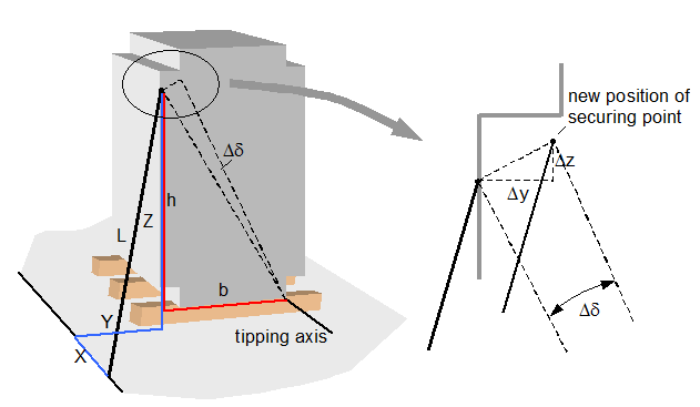 Figure 34: Direct lashing to prevent tipping Because the tilt angle is small, it is possible to determine the new position of the lashing point on the cargo unit using a simplified approach.
The three-dimensional version of Pythagoras‘ theorem provides the desired relationship between ΔL and Δδ for tilting laterally relative to the vehicle.
After additional reformulation and acceptable simplifications, we get:
Example: We shall calculate a simple example in order to demonstrate the sort of magnitude we are dealing with. A lashing is attached in a manner similar to that shown in Figure 34, with the following length components: X = 0.9 m, Y = 0.7 m, Z = 2.0 m. The length of the lashing is thus:
The lashing is a single lashing belt with an LC of 2500 daN. It has been pre-tensioned to STF = 400 daN. The change in length necessary to reach the LC is:
The distances to the tipping axis are h = 1.9 m and b = 1.2 m. This gives the tilt angle in accordance with Equation (60).
Tilting through 2.7°, for instance, causes the cargo unit to rise by some 6 cm on the side opposite the tipping axis. Top of page 2.1.2 Blocking devicesBlocking devices are subject to compressive forces. Because blocking materials are liable to be ejected to the side if forces are applied in an oblique direction, they are usually arranged in such a way that they act in precisely the direction in which the load is expected. This simplifies any consideration of the necessary movement of the cargo. This movement is of exactly the same magnitude as the change in length of the blocking material, or, more accurately, as the amount by which the blocking material must be compressed in order to transmit the compressive force in accordance with Hooke’s law. The elements involved in blocking on road vehicles comprise the boundary element of the loading platform, i.e. an elastic end wall, side wall, stanchion or special superstructure, and the filling elements, which will generally be wooden blocks, pallets or even air bags. This makes it difficult to determine an elastic constant that is anything like reliable and would make it possible to estimate the deformation from the blocking force. Furthermore, many blocking materials are rarely in full contact at the beginning of a journey, which means that if a load is applied, there is initially a small amount of unhindered movement before the opposing blocking force is established. This unhindered movement should be kept to a minimum in order to prevent the moving cargo from building up too much kinetic energy. Despite these uncertainties, we can assume that deliberate blocking, for instance using wooden beams between the cargo and the end wall would, in the event of being subjected to the load for which it was designed, only require or allow the cargo to move by a few centimetres before the entire load is taken up, which is considerably less than is the case for the majority of lashings. Top of page 2.2 Permitted pre-tensioning force for a direct lashingDirect lashings should always be positioned on two sides, so that the securing effect is established to the front and back or to the left and right. If a pre-tensioning force is applied everywhere, the securing effect of the lashings (which are generally inclined) in the initial condition is made up solely of the increase in friction between the cargo and the loading surface which is generated by the vertical components of the pre-tensioning forces. The horizontal components of the pre-tensioning forces largely cancel each other out. This means that there is initially no difference between direct lashing and tie-down lashing. The full lashing capacity LC of the lashing equipment only takes effect when the cargo has moved or become deformed as a result of an external force (generally inertial force during a braking manoeuvre or cornering) to such an extent that, on the loaded side, the force in the lashing increases by elongation from the pre-tensioning force to the lashing capacity LC and, on the opposite side, decreases to zero by contraction. The mathematical models for dimensioning a direct lashing generally found in the standards and guidelines only apply under these circumstances. These models always assume that the lashing force on the opposite side is equal to zero. In practice, these requirements are generally achieved without difficulty. The initial pre-tensioning force on both sides is important in this respect. If, for example, this is 50% of the value of LC, and if the lashing equipment is arranged symmetrically on both sides and has the same degree of elasticity, this ideal state is exactly achieved. If the pre-tensioning force is greater, a (detrimental) residual force would remain on the opposite side or the LC value would be exceeded on the loaded side. This means that a pre-tensioning force of 50% of LC is the limit case for mechanically symmetrical arrangements. The VDI 2702 Guideline, for instance, makes explicit reference to this. This limit decreases in the event of asymmetrical arrangements. It is not possible to offer a simple rule of thumb in this context. We shall explain this with an example. Example: A cargo unit has been secured to the front and back using belts with a lashing capacity LC of 1000 daN arranged crosswise and tensioned to a pre-tensioning force FT = 500 daN. The geometry of the belts is as follows:
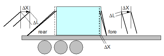 Figure 35: Asymmetrical direct lashing The two rear belts must stretch by a distance ΔL when the full lashing capacity LC is required during emergency braking.
This elongation is achieved by the cargo unit moving by the distance ΔX.
This movement causes the front belts to be shortened by ΔL.
This shortening reduces the pre-tensioning force in the front belts by ΔF.
Because the front belts were pre-tensioned to a force of 500 daN, they still retain a tensioning force of 360 daN when the rear belts have already reached their lashing capacity LC. This reduces their securing effect in the horizontal component. This reduction is, however, mitigated or cancelled out because the vertical components of the front belts make a positive contribution to the securing effect in terms of the friction value between the cargo and the loading surface. The overall securing effect of this asymmetrical arrangement is calculated in the following section. A pre-tensioning force of 50% of the lashing capacity is only rarely achieved with lashing materials, and settling effects mean that the pre-tensioning force falls slightly after a short time. This means that the problem of excessive pre-tensioning forces rarely occurs with belts. In the case of lashing chains with high-quality tensioning equipment, excessive pre-tensioning is possible using certain unauthorized tools, and must be absolutely avoided. The advice found in manufacturers‘ brochures that chain lashings should only be „hand tight“ should not, however, be understood to mean that the chains should be attached „loose“. The optimum pre-tensioning force threshold of 40% to 50% of the lashing capacity LC also applies to chains. Top of page 2.3 Securing effect of a direct lashing arrangement2.3.1 Effect against horizontal movement (displacement, deformation)As with tie-down lashings, the securing effect of a direct lashing arrangement against horizontal forces is made up of the partial effects of the horizontal component and the vertical component of the lashing force, which always acts downwards on road vehicles and thus achieves a securing effect by means of increasing the friction. Whereas the increase in friction is the dominant aspect with tie-down lashings, the lashing angle α in a direct lashing should be kept as small as possible to ensure that the more effective horizontal component is thoroughly exploited (Figure 36 left). All guidelines and standards agree that the coefficient of dynamic friction should be taken as the coefficient of friction, because there is a high degree of probability that the cargo will need to slide in order to achieve the maximum securing effect, as explained in the preceding sections. The securing effect of a direct lashing against displacement of the cargo unit is described by the following equations:
You should note that correct calculation requires that the horizontal components which have been increased by the small sliding distances ΔX and ΔY and the length L that has been increased by ΔL should be used in both equations. This is not done in any of the common mathematical models. Instead, the initial values X, Y and L are used, because the movement of the cargo is completely ignored. However, this means that the results are always on the safe side. Nevertheless, given small initial values for X or Y (which represent unfavourable securing geometry anyway), the discrepancies between the common mathematical models and the results of Equations (61) and (62) are considerable. In this respect, the simplified mathematical models are appropriate and adequate for force balance calculations. At this point, we shall calculate the securing effect for the example given in the previous section with a coefficient of dynamic friction μD = 0.3.
The conventional approach to calculation gives the following result for the same situation:
This means that the result for this example deviates by around 5% on the safe side from the result of a more precise calculation. This assessment does not take into account the dynamics of moving cargo, which somewhat increase the securing requirements. 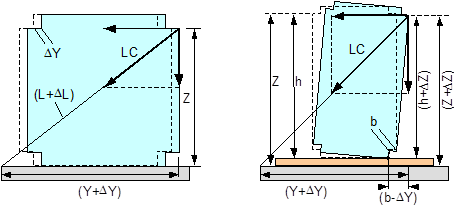 Figure 36: Securing effects against sliding and tipping Top of page 2.3.2 Effect against tippingThe securing effect of a direct lashing against tipping is also made up of the partial effects of the horizontal component and the vertical component of the lashing force. A precise calculation should take into account any possible tilting and the resulting changes to the effective forces and levers. Using the values on the right of Figure 36, the equation for the securing effect in a lateral direction relative to the vehicle is as follows:
The commonly used, simplified model is also shown for comparison purposes.
The differences between the results are generally negligible. Nevertheless, the results of the simplified models deviate towards the side that provides less safety. They are always somewhat larger than the exact results. The simplified mathematical models for tipping balance calculations are nevertheless appropriate and adequate. The securing effect of a direct lashing against tipping in a longitudinal direction relative to the vehicle is similarly calculated in accordance with Equation (63). On the right of Figure 36, you should note that the value for b in the chosen example is negative (b = horizontal distance of the lashing point on the cargo unit from the tipping axis). The vertical component of the lashing force supports the outer tilting moment. Direct lashings that are attached crosswise are therefore less effective for securing the cargo against tipping than lashings inclined at a steep angle. Top of page 2.4 Static indeterminacy with complex direct securing scenariosComplex cargo-securing scenarios can be made up of a combination of securing equipment with different degrees of elasticity, different dimensions, and acting in different directions. Under these conditions, the static load on the individual items of securing equipment is uncertain and depends entirely on the way in which each item of equipment is itself deformed by the movement or deformation of the cargo unit. It is an invalid approach to use the lashing capacity LC for each of these items of securing equipment in force or moment balance calculations. This important aspect has already been raised in the report „Securing cargo in road transport – Who knows the truth?“. In that report, a ’selective calculation approach‘ was described which allows the problem of static indeterminacy to be approximated and resolved with a sufficient degree of accuracy. The selective approach starts with the item of cargo-securing equipment in the arrangement under consideration which will be first to reach its lashing capacity in a given load scenario. On the basis of the change in length of the selected cargo-securing means, this loading is converted into a cargo movement/deformation. The latter are used to determine the changes in length of and loads absorbed by all further cargo-securing means and these values are input into a balance calculation. This calculation method is illustrated in the following section for the force balance calculation in the X direction. 2.4.1 Different lashing angles and lengthsIf several items of lashing equipment are used to secure a cargo directly with different lashing angles, different lengths and cross-sections and different pre-tensioning forces, one must first identify the most „sensitive“ item, i.e. the one which reaches its lashing capacity LC with the smallest amount of movement of the cargo. Because this task does not demand extreme accuracy, the simplified equations (59) are used to convert ΔL to ΔX. Equation (55) is first used to determine the necessary change in length ΔL for each item of lashing equipment.
The reformulated Equation (59) gives the associated ΔX for each of the items under consideration and the resulting smallest value for ΔXmin.
The following equation then gives the expected loads FW for the remaining items from ΔXmin:
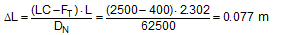
We shall demonstrate this calculation sequence on the basis of a simple example. A cargo unit is secured against sliding in the direction of travel with six direct lashings (Figure 37). Three different types of lashing are used in this scenario, each of which comprises different components. The lashing belts chosen have a lashing capacity LC of 1000 daN and a nominal elastic constant DN of 25000 daN. The calculation is performed using a spread sheeting program. 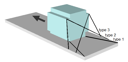 Figure 37: Complex direct lashing The table in Figure 38 shows the results, assuming that the same pre-tensioning force of 400 daN was applied to all the belts. The Type 1 lashings reach their lashing capacity of 1000 daN after the cargo has moved in a longitudinal direction by a distance of ΔX = 0.055 m. This distance is only sufficient to increase the load on the Type 2 lashings to 614 daN and on the Type 3 lashings to 697 daN. This means that the total securing effect is reduced correspondingly. 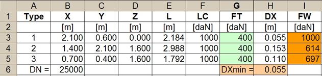 Figure 38: Distribution of the applied load with the same pre-tensioning forces If a lower pre-tensioning force is applied to those lashings that reach their lashing capacity first, and a greater pre-tensioning force is applied to the rest, it is possible to increase the „yield“ in terms of securing effect. This has been done in Figure 39, although the unavoidable consequence of this is that under these conditions the cargo unit must slide by a distance of ΔX = 0.077 m in order to bring the Type 1 lashings up to their lashing capacity of 1000 daN. Given the somewhat greater pre-tensioning force, the other lashings nevertheless achieve around 80% and 92% of their capacity. 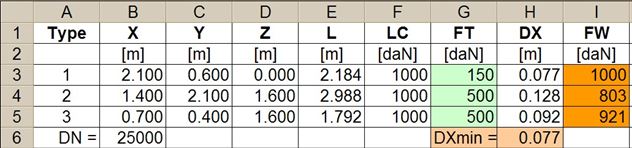 Figure 39: Distribution of the applied load with adjusted pre-tensioning forces If the commonly used guidelines and standards had been followed, all three types of lashing would have been assigned a load of LC = 1000 daN. Top of page 2.4.2 Different securing materialsSimultaneous use of different securing materials, e.g. belts and chains, also leads to a loss of securing effect due to the different elastic constants. The more elastic securing materials will always be loaded below their lashing capacity when the more rigid securing materials have already reached their load limit. This effect is particularly dramatic if „rigid“ blocking material is used in conjunction with elastic lashing belts. The classic example of this is when a heavy cargo is secured against sliding forwards by making use of the end wall of the loading platform. The DIN EN 12642:2007 standard specifies the following load capacity for end walls: 0.4 x the payload weight up to a maximum of 5000 daN for standard superstructures (Code L) and 0.5 x the payload weight for reinforced superstructures (Code XL). The standard also specifies the maximum permitted elastic deformation during type testing. However, this specification is extremely general in nature and does not allow us to make realistic assumptions about the deformation of an end wall that can be expected if its load capacity is exploited. If only the lower part of the end wall is subjected to a load, it is „less sensitive“ and will only deform by a few centimetres when its capacity is fully exploited. If the entire height of the end wall is subjected to a load, which assumes a certain amount of deformation of the cargo, the permitted deformation is likely to be in the region of decimetres. This deformation can be interpreted as the distance ΔXmin, making it possible to estimate the loads to which belts that have been used in parallel will be subjected. Equation (64) can be used for any belt or chain in this situation.
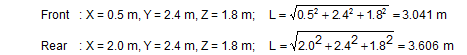
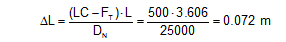
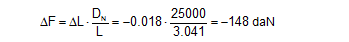
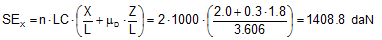
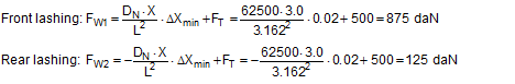
Example: The securing scenario shown in Figure 40 combines tie-down lashing, direct lashing and blocking against sliding in a forward direction. There is no doubt that the blocking represents the most rigid equipment used. Because the load is only applied to the very bottom of the end wall of the vehicle, it will only yield slightly. A value of ΔX = 0.020 m is used as an estimated value for the distance travelled by the cargo during an emergency braking manoeuvre after which the end wall reaches its load capacity, also taking into account other yielding effects. 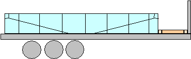 Figure 40: Securing in a longitudinal direction by means of tie-down lashings, direct lashings and blocking The effect of the longitudinal lashing will be investigated using these estimated values. The data is as follows: X = 3.0 m, Y = 0.0 m, Z = 1.0 m, L = 3.162 m, LC = 2500 daN, DN = 62500 daN, FT = 500 daN. The same data applies to the lashing to the rear. The force FW that is present after the cargo has been displaced forwards by a distance of ΔX = 0.020 m is calculated for both lashings using Equation (64).
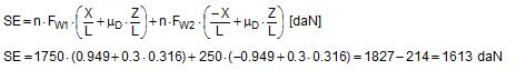
The movement is so slight that the two lashings to the rear do not lose all force. In simplified form, the overall securing effect for all four lashings in the event of an emergency braking manoeuvre is as follows given the dynamic coefficient of friction μD = 0.3:
Failure to take into account the static indeterminacy and unquestioning adherence to the commonly used standards and guidelines would have attributed the lashing capacity LC to each of the direct lashings to the front and would have regarded the lashings to the rear as slack. The overall securing effect resulting from this would have been:
The difference is so dramatic that it would seem sensible to deal with such statically uncertain securing scenarios appropriately in the guidelines and standards(9). |


|
Top of page
| Contents
| |