
4. Additional tipping moment due to the rotational inertia of cargo units |
[German version] |
The mathematical model used in the Annex 13 for assessing the suitability of a securing arrangement describes a physical cargo unit by its mass concentrated in its centre of gravity. This is fairly accurate as long as the spatial dimensions of the unit remain below about 10 metres. Any tipping moment will then be determined by the vertical distance of this centre of gravity to the edge of the footprint, i.e. the tipping axis of the unit. Larger units, however, will develop a substantial additional tipping moment by their rotational inertia against the rotational acceleration of the ship in rolling or pitching motions. This additional threat should be included into tipping balances for extra large cargoes by a simple algorithm.
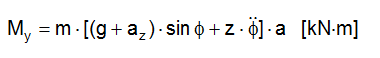
The ordinary transverse tipping moment My, analogous to the algorithm of the Annex 13, but without the contribution of wind and spray forces, reads:
In this simple approach the mass m is concentrated in the centre of gravity of the cargo item. The real spatial mass distribution requires the compilation of infinitesimal mass elements with their individual distances from the centre of gravity. This is indicated in Figure 3.1. The differential tipping moment dMy of each infinitesimal mass element dm reads:

The integration of all differential tipping moments over the full mass m of the cargo item with g, az, z, a, b as constants and e, f as variables results in the true tipping moment:
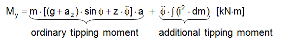
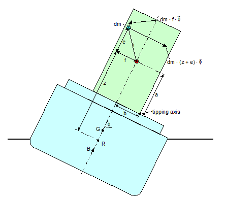
Figure 4.1: Integration of differential mass moments
The additional tipping moment is independent from the position of the tipping axis and the level of stowage in the ship. The figures of a and z have no influence.
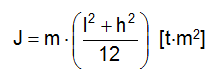
The term ∫(i2 · dm) represents the rotational moment of inertia J about an axis through the centre of gravity. Its numerical value is measured in t · m2. It should be provided by the manufacturer of the cargo unit about the longitudinal axis (rolling) and the transverse axis (pitching). However, these data are generally not available and may be approximated.
For a box-shaped unit of the length l, width w, height h and homogeneous mass distribution the rotational moment of inertia about an axis through the centre of gravity is:
For rolling:
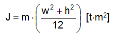
For pitching:
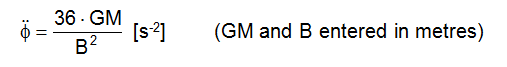
The rotational accelerations for seagoing ships may be approximated as follows:
For rolling:
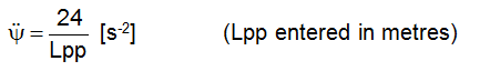
For pitching:
m = mass of cargo unit [t]
dm = mass element of cargo unit [t]
g = gravity acceleration [m/s2]
aZ = temporary vertical acceleration, which virtually increases the gravity [m/s2]
φ = roll amplitude [rad]
z = vertical distance of cargo centre of gravity from roll axis of vessel [m]
a = tipping lever [m]
e = vertical distance of mass element from axis through centre of gravity [m]
f = transverse distance of mass element from axis through centre of gravity [m]
i = direct distance of mass element from axis through centre of gravity [m]
J = rotational moment of inertia [t · m2]
GM = metacentric height of the ship [m]
B = breadth moulded of the ship
Lpp = length between perpendiculars of the ship [m]
l = length of cargo unit [m]
w = width of cargo unit [m]
h = height of cargo unit [m]
![]() = maximum rotational acceleration of the vessel from rolling [s-2]
= maximum rotational acceleration of the vessel from rolling [s-2]
![]() = maximum rotational acceleration of the vessel from pitching [s-2]
= maximum rotational acceleration of the vessel from pitching [s-2]
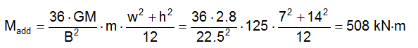
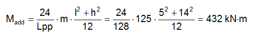
Example: A huge piece of structural framework of 125 t and the dimensions l = 5 m, w = 7 m and h = 14 m is loaded on the hatch top of a heavy lift vessel (Figure 3.2). Vessel data are Lpp = 128 m, B = 22.5 m, GM = 2.8 m. The additional tipping moments Madd are:
About the longitudinal axis (rolling):
About the transverse axis (pitching):
| Top of page | Contents |