
3. Vessel survival criteria in case of a major cargo shift |
[German version] |
There have been innumerable ship losses and near losses due to a major cargo shift. Thus it suggests itself that well established regulations are in place for avoiding such accidents with cargoes where the risk of shifting is evident, like fine-grained bulk cargoes. For other solid cargoes such regulations do not exist and any regulations on intact stability are based on the assumption that the cargo does not move during the voyage.
However, severe accidents with total shift of the cargo onboard Ro-Ro vessels have produced considerable heeling angles which disabled the ship and finally caused sinking. Therefore the Lashing@Sea consortium has proposed to evaluate a total cargo shift criterion for cases where cargo securing shall be deliberately reduced according to favourable environmental conditions. The evaluation should be guided by the ship’s Cargo Securing Manual and ensure the compliance with specific criteria, before the reduced securing arrangement is accepted.
Possible arguments against such a safeguarding may refer to the basic aim of the CSS-Code, which is to avoid shifting of cargo in the first place, and express the inherent fear that the fulfilment of a survival criterion might lead to conceding a higher risk of shifting. This would be indeed unacceptable with the carriage of dangerous goods. On the other hand, weather dependent securing of cargo has been practiced for years and the application of a survival criterion for certain ships should be looked at as an additional and valuable safety measure. The accommodation of such a survival criterion in an appropriate Code should be left to the decision of IMO bodies.
The evaluation of a total cargo shift incident should be based on the assumption that all cargo units on board move to one side until they are packed tightly to each other without any void space in between. For this ultimate condition the curve of the total heeling levers should be drawn and intersected with the currently actual curve of righting levers. The intersection shows the static heeling angle and the residual righting levers used for the compliance assessment.
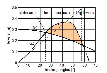
Figure 3.1: Heeling levers h(φ) versus righting levers GZ
The curve of the total heeling lever follows the function
h(φ) = heeling levers [m]
M0 = total heeling moment at φ = 0° [t · m]
DISM = actual mass displacement [t]
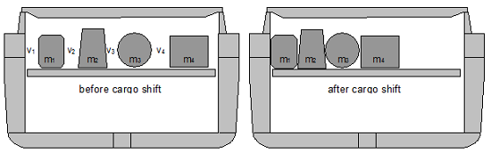
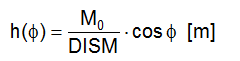
Figure 3.2: Heeling moment from shifting of break bulk cargo
The total heeling moment M0 is the sum of the sectional heeling moments in all cargo sections of the vessel. The sectional moment in Figure 3.2 is obtained by:

In Ro-Ro vessels, where the mass of cargo with intermediate voids is fairly homogeneously spread over the width b of cargo spaces, the shifting distance d of the common cargo centre of gravity is obtained by the approximation: d = b/2 – (b – v)/2 = v/2.
The sectional heeling moment is then:
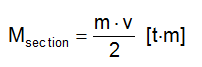
m = mass of all cargo units in a particular section [t]
b = width of cargo space [m]
v = sum of all transverse voids [m]
The following functional issues should be considered before accepting the pre-calculated heeling angle:
- On-board systems getting out of order at the obtained heeling angle.
- Openings on board being submerged at the obtained heeling angle.
- Possible measures to save human lives, the ship and the cargo.
The following stability criteria should be fulfilled immediately after the heel has been obtained and before any counter-ballasting measures are taken:
- The static angle of heel after a total cargo shift shall not exceed 25°. This may be increased to 30° if the deck edge is not submerged.
- The righting lever GZ has at least 20° positive range beyond the static angle of heel.
- The maximum GZ reaches at least 0.1 m within 10° beyond the static angle of heel.
The following stability criteria should be fulfilled after counter-ballasting measures are completed:
- The static angle of heel shall not exceed 15°. This may be increased to 17° if the deck edge is not submerged.
- The righting lever GZ has at least 35° positive range beyond the static angle of heel.
- The maximum GZ reaches at least 0.2 m within 20° beyond the static angle of heel.
- The area between the heeling lever curve and the righting lever curve beyond the static angle of heel shall be at least 0.075 m · rad.
The necessary computations for obtaining the total heeling moment and the parameters of residual stability may be facilitated by suitable computer software associated to the on-board stability computer.
| Top of page | Contents |