
| Photo of the month – February 2026 |
[German version] |
Seen by chance, in a traffic jam. When the load securing is so obviously wrong that you hardly need to do the math.
When you are sitting in a traffic jam on a German motorway, blissfully unaware of anything untoward, you may sometimes happen to notice something that really shouldn't be ignored.
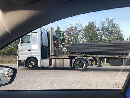
Figure 1 [Marc Sommerfeld]
This contribution to our “Photo of the month” series shows that everyone can take part. We invite all our readers to send in their own photos. The things you see when you're out and about help raise awareness of the topic and improve the quality of load securing.
What can't be seen in the photo is the way the load extends into the rear part of the loading bed. That is why we add the following description of the scene witnessed by the photographer:
- Sheet pile panels were loaded in three adjacent stacks on the loading bed.
- The panels were not stacked flush one above the other in the direction of travel. They extended right up to the rear end of the trailer, with the result that, overall, the position of the vehicle’s center of gravity appeared uncritical.
- The load was tied down with a total of three chains, together with a single additional chain at the front to prevent the panels from slipping forwards. However, this front chain had only been passed over a part of the load.
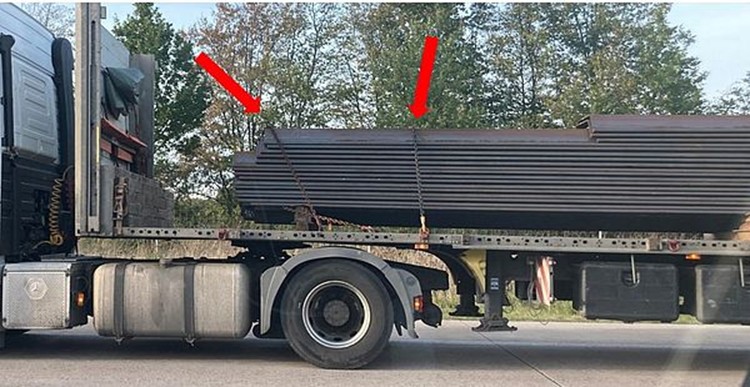
Figure 2 [Marc Sommerfeld]
There is clearly a large gap between the load and the end wall. Gaps like this often indicate shortcomings in the way the load is secured, even though, in theory, they can be compensated for by other measures. In the present case, a chain had been attached to protect against forward movement, although its effectiveness appears debatable.
The width of the load did not correspond to the width of the loading bed. There were three separate stacks standing next to one another. To secure these correctly, it would have been necessary to secure each stack separately. Using the method chosen here, each chain only acts on the panels that it is in direct contact with. The sheets in between are simply held in place by the clamping force and friction. This is vitally important because the middle sheets are less firmly secured and can slide forward out of the stack when the vehicle brakes. This effect is known as telescoping.
The photos cannot reliably tell us whether this was the situation when the sheets were loaded or whether it arose due to braking maneuvers during the journey.
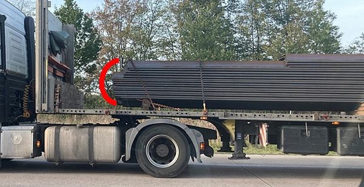
Figure 3 [Marc Sommerfeld]
Our eyes cannot help being constantly drawn to the gap between the load and the end wall. And that makes it easy to overlook the top three layers of sheets in the middle of the loading surface.
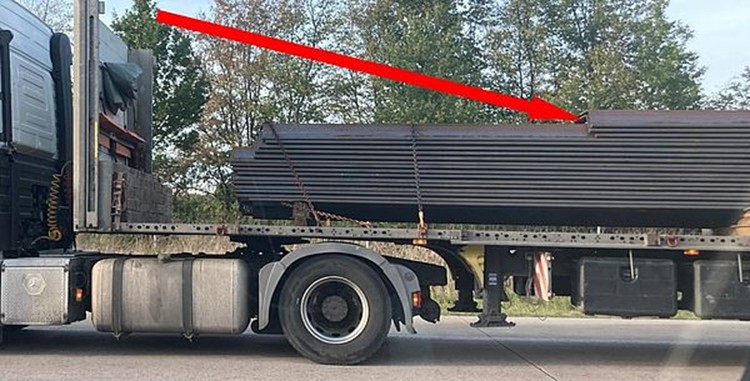
Figure 4 [Marc Sommerfeld]
These three layers were secured by means of only two (!) tie-down chains. These are outside of the section of the vehicle shown in the photo.
It seems natural to ask whether this can be sufficient to secure the load.
A calculation of the forces involved shows that a minimum of five tie-down chains would have been needed to secure these topmost layers. But in the case at hand, only two were used. If we consider the total load carried by the vehicle, then 45 chains would have been needed to absorb the braking forces in an emergency
How do we arrive at this number? Let us consider the top three layers, which are not directly secured to the front in any way:
We assume that the topmost sheet pile panels are ten millimeters thick, fifty centimeters wide and eight meters long. Given a stowage value of 7.85 tonnes/m³, we obtain a weight of approximately 314 kg per sheet. Three sheets on top of one another in each of three adjacent stacks result in a presumed weight of 2826 kg.
For the purposes of the load securing calculations, we make the following assumptions:
- To ensure we err on the safe side, we estimate the coefficient of friction for steel on steel as µ = 0.1
- The securing coefficient (formerly known as the K factor) is assumed to be 1.6* (in accordance with DIN EN 12195-1)
- The pre-tensioning force per chain is 2500 daN
- The angle of the chain to the loading surface is 90 degrees
- The required acceleration during emergency braking is equal to 0.8 g
Load securing is adequate whenever the securing forces are greater than the forces that arise. The following example illustrates the force balance calculation that can be assumed when braking.
Arising forces < Securing forces
Arising forces < Friction + Securing
0.8 x m x g < m x g x µ + n x k x TF x µ x sin(a)
In this example:
0.8 x 2826 kg x 9.81 m/s² < 2826 kg x 9.81 m/s² x 0,1 + n x 1.6 x 2500 daN x 0.1 x sin(90°)
*Trained users will undoubtedly be perfectly familiar with the standard, as they will also be with the fact that it no longer contains any “K factor”. However, it is possible to determine the maximum “K factor” based on these assumptions if we combine the numerical value “2” from the numerator with the safety factor fs = 1.25. For the sake of clarity, we have simplified the steps involved in the calculation here and adhere more to logic than to the formula.
2 / 1.25 = 1.6
On the basis of the values assumed above, we now solve for the number of required tie-down chains „n“:
2217.85 daN < 277.23 daN + n x 400 daN
1940.62 daN / 400 daN < n
4.85 < n
This calculation shows that a minimum of five chains would have been needed just for the top three layers of the sheets lying a little further to the right.
If we use the same approach for the maximum assumed load of approximately 26 tonnes, then we find:
0.8 x 26 t x 9.81 m/s² < 26 t x 9.81 m/s² x 0.1 + n x 1.6 x 2500 daN x 0.1 x sin(90°)
On the basis of the values assumed above, we now solve for the number of required tie-down chains „n:
20404.8 daN < 2550.6 daN + n x 400 daN
17854.2 daN / 400 daN < n
44.6 < n
Our calculations therefore show that in the event of emergency braking at full load, a minimum of 45 tie-down chains would have been required. In reality, only three were used.
How could the load securing have been improved?
- Squared lumber could have been inserted to block the gap between the end wall and the load.
- The individual sheets should have been flush and been resting against an appropriate support in the forward direction.
- Friction-enhancing material should have been used in every intermediate layer.
What can we learn from this?
- Over the coming period, we shall take passengers with us so that we can collect better photographic documentation.
- We encourage everyone involved in cargo transport to calculate their load securing requirements. Calculations are not difficult to perform, prevent loss and damage, and save lives.
Your load securing columnists wish you a wonderful February.