
| Photo of the month – July 2023 |
[German version] |
“Layered” cut lumber with a swing in its hips
This month, we have a very dynamic photo for you because the load – as so often happens – is on the move. And it really does look rather as if the load here is “swaying its hips”.
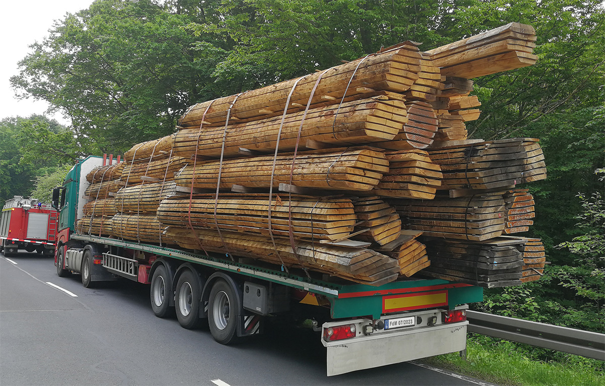
Figure 1 [Martin Lang]
The load:
It is layered cut lumber. However, the term “layered” is simply the one that occurred to us and we would not like to claim that it is technically correct. However, it does very neatly express the fact that the wood, which has been sawn into thick planks, has been separated using wooden slats and stacked, looking just as it did when the tree was growing. This necessarily produces oval structures because a tree, which has a circular shape when it is growing, extends only in one direction (vertically). Why do we mention this? Because this greatly increases the danger of tipping.
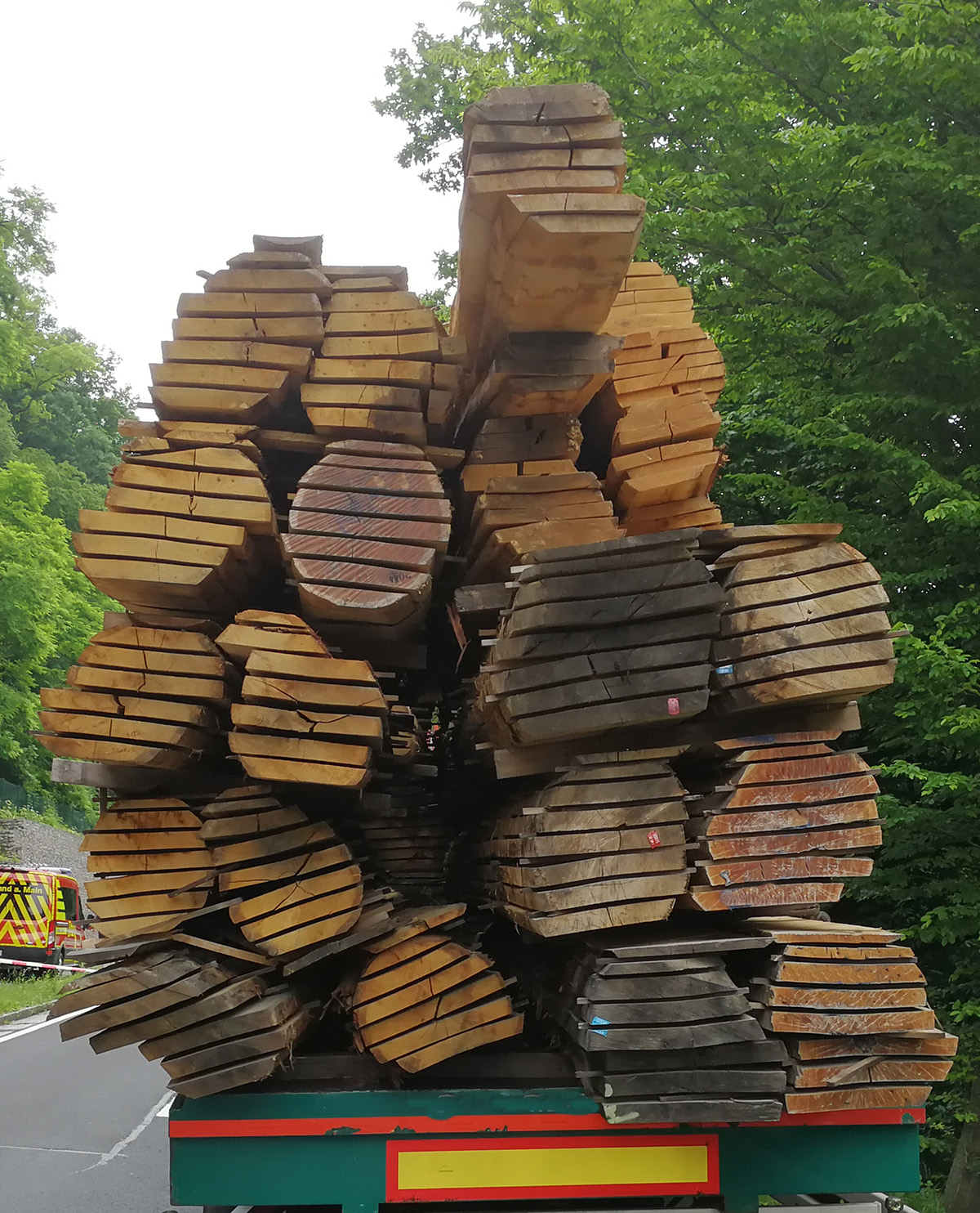
Figure 2 [Martin Lang]
This lumber is actually a very nice load. It is rough-sawn and therefore has a coefficient of friction of at least μ = 0.4. Assiduous load-securing experts will be pleased with this because we are lacking only μ = 0.1 to the sides and at the rear. That could easily be taken care of using tie-down lashings.
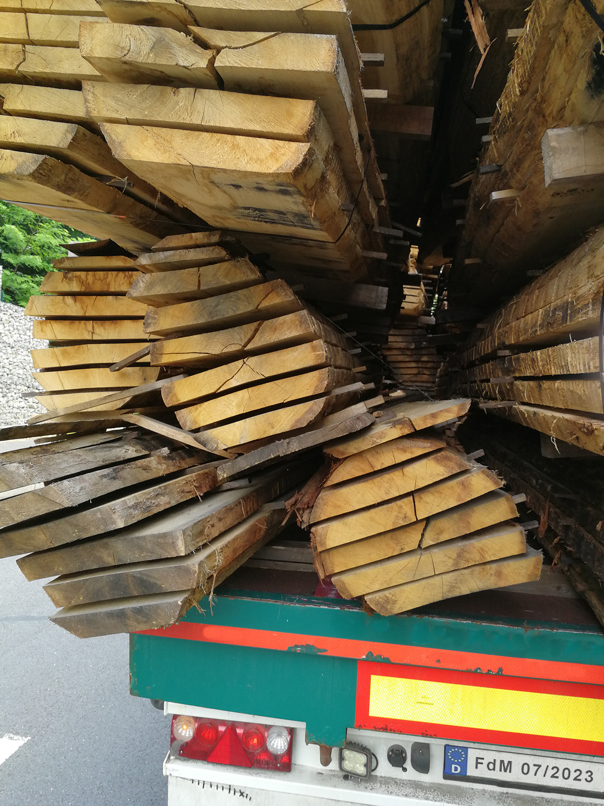
Figure 3 [Martin Lang]
However, if we look at the load a little more closely, we can easily see one area where things started to come unstuck! If a load like this is to be stacked in a way that forms a more or less compact load unit then it is necessary to use robust dunnage that extends all the way across. The challenge then is to find a way to make the height of the load as uniform as possible. If that is not possible simply using the load itself then board sections must be used for equalization. This dunnage, which should preferably have a rectangular cross-section, gives the load stability and must be inserted tree-shaped layer by tree-shaped layer.
To secure the load at the side, we recommend using loop lashings, as we so often do. These have the advantage of combining tight-fit securing with a tie-down component. Naturally, they must always be guided around the load from both sides. Therefore, at least twelve loop lashings are needed. We assume that the total weight of the load is approximately 24,000 kg, subdivided into three stacks of 8,000 kg each. The four loop lashings per stack provide a securing force of approximately 8,000 daN on each side. Any losses due to angles are compensated for by the assumed friction of µ = 0.4. These measures ensure that the load is secured to the side.
As far as the securing to the front is concerned we see that there are additional stanchions at the end wall. Since we have no information about the strength of the stanchions plus end wall, we assume the strength of a Code XL vehicle (13,500 daN). Given a complete load of 24,000 kg, we need a securing force to the front of 0.8g = 19,200 daN. The friction produces a securing force of μ = 0.4, which corresponds to 9,600 daN. As a result, no further securing is needed to the front.
The total of twelve loop lashings produce 12 x 400 daN x μ = 0.4 = 1,920 daN of securing force. With regard to the loop lashings, we can only count one side, namely the pre-tensioned side, along with the tie-down lashings. With the end wall, the friction and the loop lashings to the side, we now have adequate securing force for the direction of travel and lateral securing.
We only need some more tie-down lashings to secure the load to the rear. We decide to use another three tie-down lashings with long-lever ratchet handles, which are easily able to supply the missing securing force of 480 daN.
Why do we not use any anti-slip material?
This is definitely not an option here because it would have to be laid between each board.
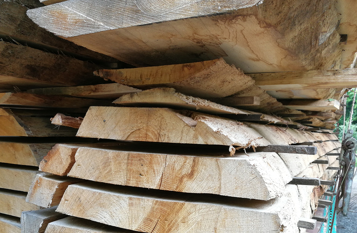
Figure 4 [Martin Lang]
Figure 4 illustrates very nicely why the structure, as it was, proved to be so unstable. The contact surfaces between the “trees” are very small and the dunnage that has been used is much too feeble. Figure 3 shows the broken dunnage. As a result, the load was not able to hold together.
Your load securing columnists wish you an enjoyable summer and a safe and secure journey at all times.
Back to beginning