
| Photo of the month – June 2023 |
[German version] |
The physics of curves….or did someone skip their physics classes?
To mark the start of summer, we are serving up a particularly tasty morsel for our readers. In itself, a 16.05-tonne concrete beam is not an easy thing to secure, even without anything else getting in the way. Abrasive edges, high mass, sensitive to transport and extremely liable to tipping. All in all, something of a challenge – but nevertheless one that can be overcome.
This Photo of the Month is particularly instructive because the person who sent it to us was kind enough to send another one of an identically laden vehicle as “additional information”. This allows us to see in detail how the load was secured and what conceptual errors were made during its securing. So straightaway, we want to say: “Thank you very much” for being so attentive.
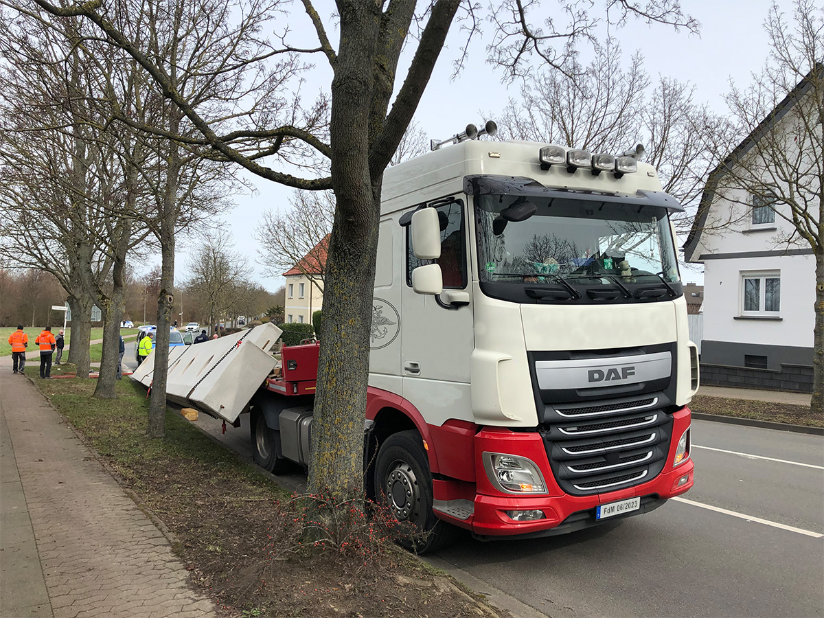
Figure 1 [Niklas Rast]
At first glance, all we can learn from these photos is the following:
- In a left-hand bend, the load slid off to the right from the extendable drop-deck trailer – much as might have been expected.
- The vehicle parts that can be seen lying around suggest that other attachments were present on the trailer due to the gooseneck.
- It is all but certain that the damage suffered by the concrete beam in this incident will have rendered it unfit to ever span over any hall.
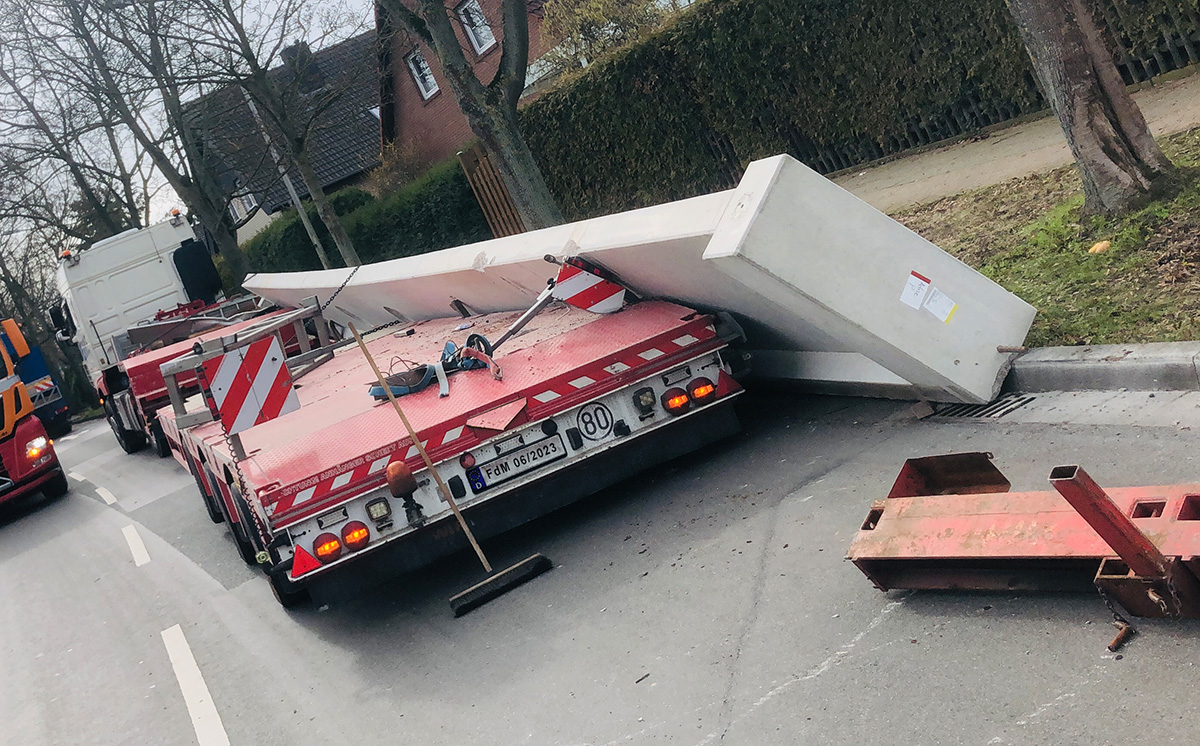
Figure 2 [Niklas Rast]
It can be clearly seen that the beam is slightly curved, somewhat in the shape of a bridge. It also appears that the heavier part of the beam was facing upwards, probably because this is exactly how it would have been used on the building site. This represents another challenge for load securing.
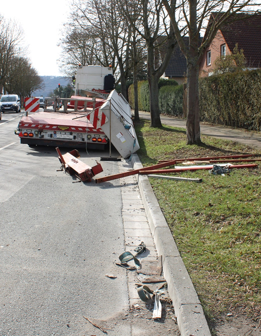
Figure 3 [Niklas Rast]
The load securing equipment found at the scene clearly confirmed that the securing measures were inadequate to prevent the loss of the load. Stanchions and belts are lying on the street and the chains that can be seen on the vehicle have been transformed into “direct lashings”. A broken chain can be seen at the back of the vehicle and, at the front, two chains are just about still holding the beam. The task performed by the belts can be seen in the following photos.
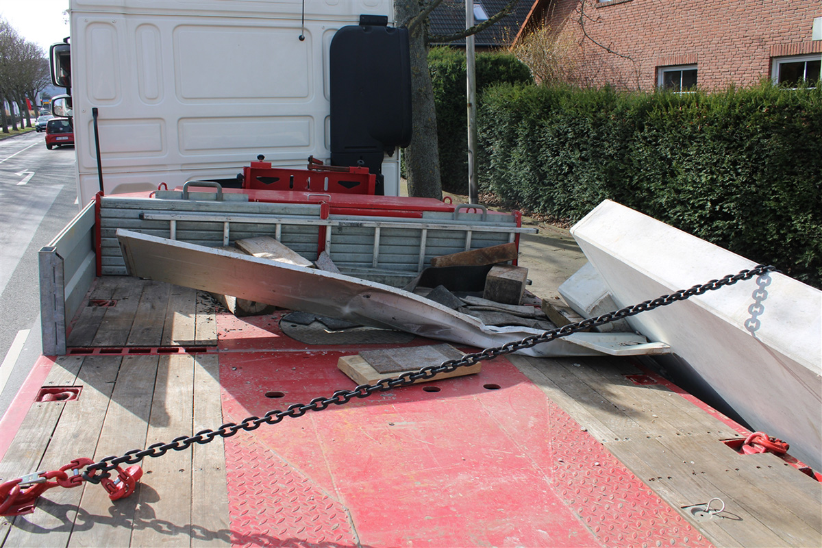
Figure 4 [Niklas Rast]
Figure 4 clearly shows how what was presumably a tie-down lashing has involuntarily been transformed into a direct lashing (loop lashing). Even though this “direct lashing” was created due to the dynamics of the incident, it could, at least in part, have prevented the complete loss of the beam. This shows just how effective such securing arrangements can be. If they are used correctly… But more of that later.
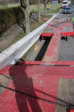
Figure 5 [Niklas Rast]
Now, let us take a look at the empty loading bed. The two involuntarily formed direct lashings can be clearly seen.
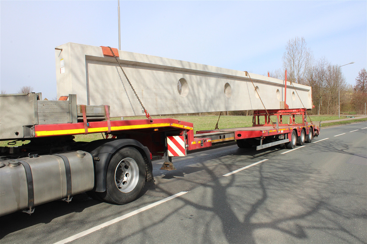
Figure 6 [Niklas Rast]
And here, as promised, is the second vehicle:
This Figure gives us the answer to the question: How was the load actually secured? As luck would have it, the vehicle involved in the accident was followed by an identically laden one, meaning that we have a textbook explanation for what occurred.
Securing:
- The load of 16.05 tonnes was secured using three tie-down lashings. This raises the question of whether those responsible for loading were worried that the load might fly away upwards.
- Regarding the securing to the front, we are told that the beam might have been loaded as a tight fit against the thick wooden block … (this is what is suggested by Figure 4); in Figures 8 and 9, we can see how the beam was loaded on the second vehicle. Something of a tight fit against what might be ramps and with anti-slip material above and below the timber used to distribute the pressure – all of which is very positive.
- Securing to the sides is “ensured” by stanchions on the support structure.
- The remaining gaps were filled in with timber. Just how this was fixed in place is impossible to determine and it might not have been fixed at all.
- The supporting base used at the rear of the vehicle consists of two parts. On the one hand, a square-tube structure and, on the other, an attachment that held the stanchions and which was, at least in part, joined to the lower element as a tight fit. Figures 10 and 11 do not allow us to tell exactly how this was done.
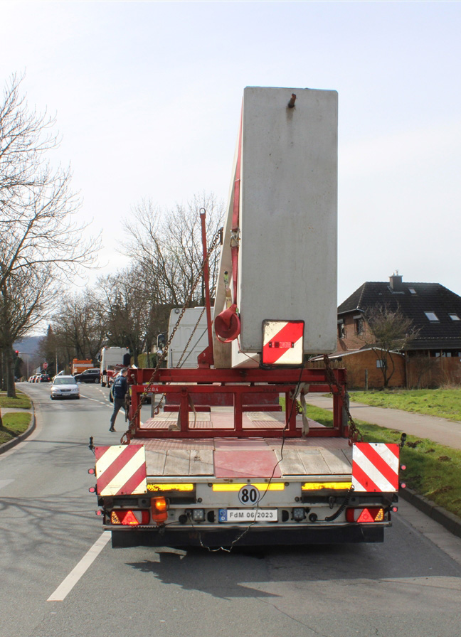
Figure 7 [Niklas Rast]
We have no information about why the beam was loaded off-center. It does at least look as if the beam was already leaning a little to the right.
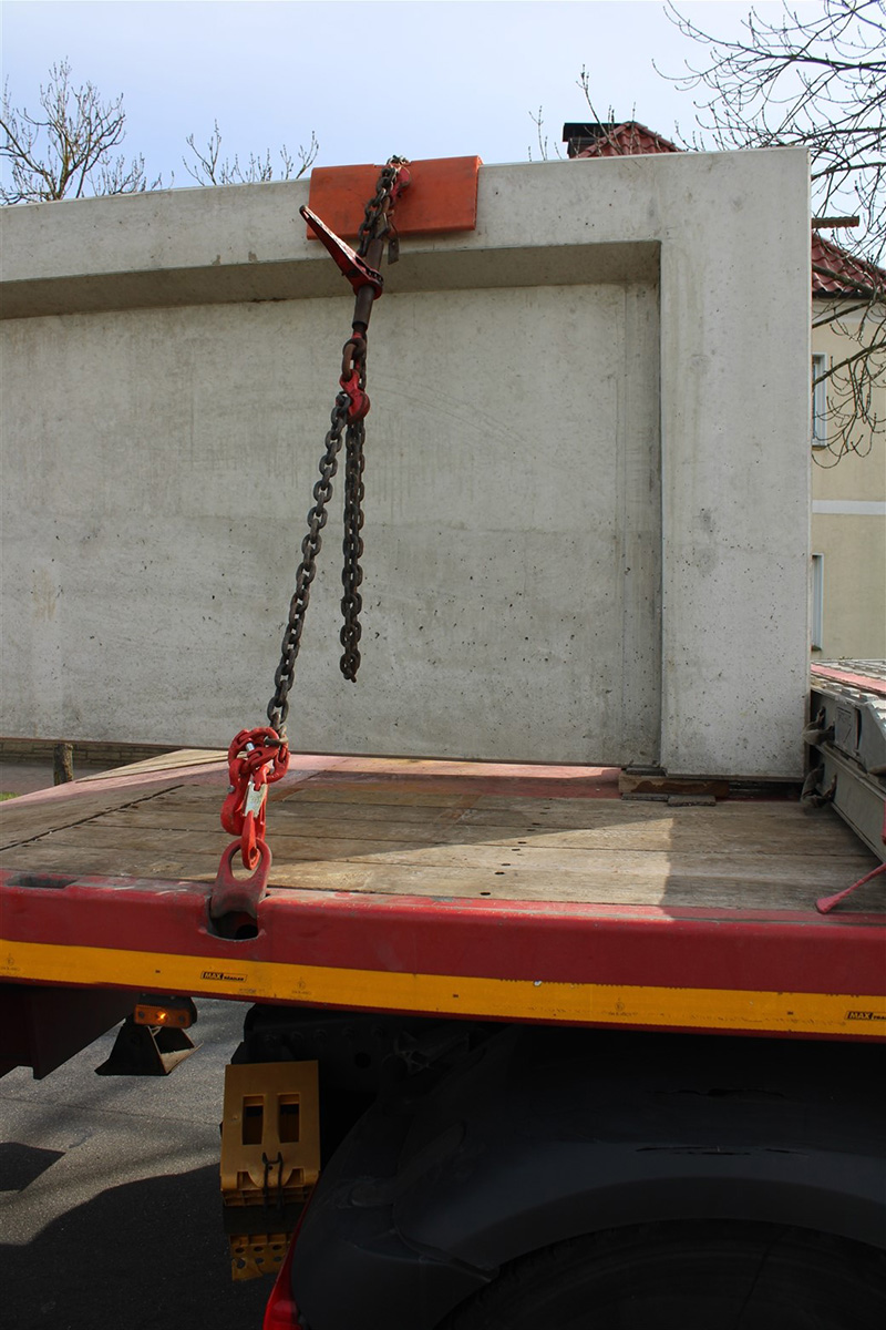
Figure 8 [Niklas Rast]
Here are the “securing arrangements” at the front. If these are ramps then they are not suitable for absorbing point loads to the side. If a tight fit is to be used here then this must also be able to transmit the forces into the vehicle.
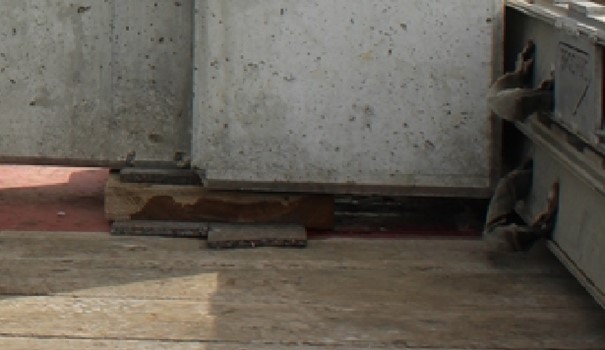
Figure 9 [Niklas Rast]
As far as we can tell from Figure 9, anti-slip material was used above and below the timber. If this took the form of heavy-duty mats then that is one very positive aspect.
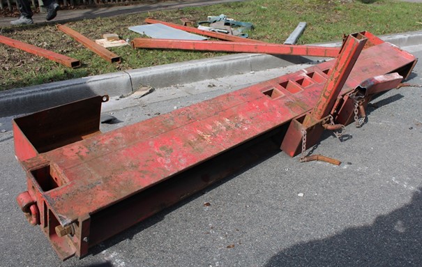
Figure 10 [Niklas Rast]
Figure 10 shows what is fundamentally a very good structure since it clearly provides several stanchion sockets that make it possible to transport and secure loads of different widths. However, caution should always be exercised when using stanchions because their load securing capacity is very often completely overestimated. In the lower area, it is possible to secure some 3,000 to 4,000 daN. However, this securing capacity falls dramatically even at the height of just one meter. The manufacturers have produced charts that provide extremely precise information on the loads to which the stanchions are subjected in different locations (over the loading surface).
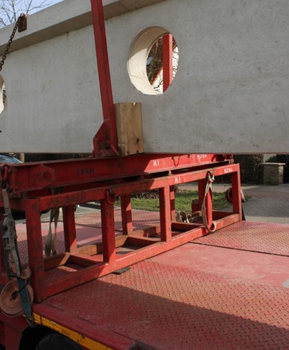
Figure 11 [Niklas Rast]
In Figure 11, we once again see tie-down lashings. Although these are good for holding the frames together vertically, they cannot secure the load because there is no friction. The small patches of anti-slip mats are merely there to keep up appearances – and they barely manage to do even that. The friction can therefore be considered to be steel on steel (µ = 0.1 or 0.2), meaning that 60% or 70% of the required securing force is missing to the front and 30% or 40% to the sides.
Securing the load:
Let us start by saying that we do not generally work our way step-by-step through the standards, but instead always attempt to design securing solutions that are as practical as possible in use. According to the standards, if you use enough tie-down lashings then you can secure the load against tipping. However, a different solution suggests itself for this load.
Friction:
- We naturally recognize the value of having adequate friction in this securing solution even though, this time, it plays a subordinate role.
- We place anti-slip material under the square-tube frame so that it is completely isolated from the loading surface in terms of friction, and
- we place anti-slip material under the contact surfaces on the top loading frame.
- The end that is lying on the gooseneck is provided with anti-slip material as shown in Figure 9.
Danger of tipping:
- This load is at particular risk of tipping and it is necessary to take this fact into account.
- Due to the geometry of the beam, we have decided to secure it twice using four loop lashings.
- To do this, we will make use of the circular holes in the beam. One loop lashing at the bottom on each side around the beam and through the hole, and
- one loop lashing on each side through the hole and up and around the beam.
- If there are not enough load securing points in the corresponding locations then the pairs of loop lashings can also be distributed over two holes.
- These doubled loop lashings hold the beam in its vertical position by acting as direct lashings.
- The choice of whether to use chains or belts has to be decided at the loading site. The photos do not allow us to tell whether or not a belt is passed through a hole.
- It is important to protect the load against the chains or protect the belts from the abrasive concrete in some way, preferably using protective sleeves.
- If loads of this type are transported regularly and they are to be secured using chains, then tube sections with a rounded collar (flange) could do an excellent job. These would be inserted into the holes from both sides and stuck together at the contact surfaces using anti-slip material. It might be possible to do something similar using plastic.
- At the top and bottom edges, it would again be necessary to use edge protectors, possibly as shown in the photo, and these might have to be secured with belts.
- Belts with protective sleeves might be easier to handle. If they have to be passed through the hole then lifting slings might be of assistance. This also applies to chains.
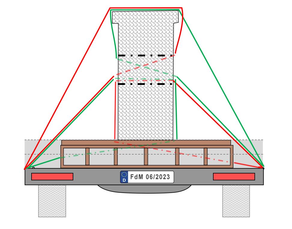
Diagram 1 [TIS]
Load securing to the front.
- Because the beam should only move a minimum amount even when subjected to a load, we use a combination of friction and direct lashings to secure it.
- If we simply rely on friction, then 3,200 daN of securing force are still missing to the front.
- We decide to use a chain with an LC of at least 5,000daN. We use a chain to keep the stretching of the load securing equipment as small as possible, meaning that the beam only has to move a minimal amount when subjected to a load in order to develop sufficient securing force in the direct lashing.
- This, of course, presupposes that the vehicle has load securing points with an LC of 5,000 daN (or more).
- We guide this chain around the base of the beam, naturally with adequate edge protection. To ensure that the beam does not slip, we place it on a piece of squared lumber, which we position in front of the beam and fix in place with a belt or a nailed join.
- At 8 m or even 10 m, the chain we have chosen is long enough to ensure an effective angle.
- The chain is pre-tensioned and now secures 10,000 daN (minus the slight loss due to the angle).
- We have now more than adequately secured the load to the front using just one correctly positioned chain.
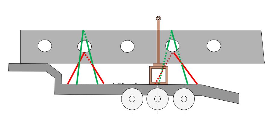
Diagram 2 [TIS]
For reasons of clarity, the side view shows only half of the required loop lashings. At the front are the loop lashings that hold the load on the left-hand side of the vehicle and at the back are the loop lashings that hold it on the right-hand side of the vehicle. It is indeed necessary to attach all four loop lashings at the front and back as shown in Diagram 1.
Existing securing using tie-down lashings and stanchions
- The existing securing arrangements can be kept.
- The chains provide a minimum level of securing and can be attached relatively quickly during the loading process (occupational safety!!!)
- The tight fit at the base of the beam due to the stanchions is a sensible precaution.
- Securing of the load to the rear is ensured by friction and the minimum securing force.
Your load securing columnists wish you a relaxing, safe and secure summer!
Back to beginning