
| Photo of the month – December 2022 |
[German version] |
Round steel bars, heavy and dangerous
The first photo is enough to dash any expectation we may have of a good securing job. It must be winter, as we can see a little snow melting on the loading bed. Which makes this an ideal case study for this advent season.
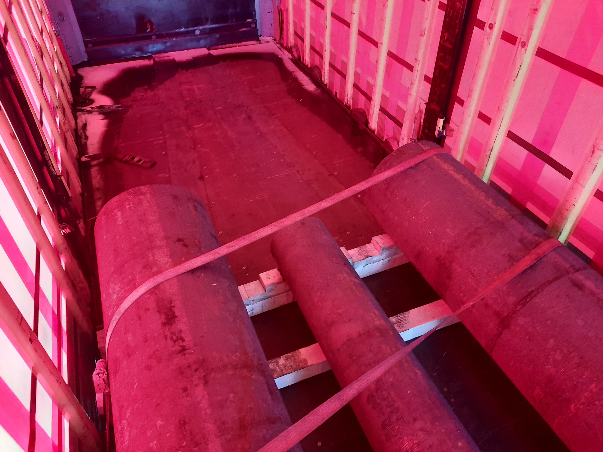
Figure 1 [Raymond Lausberg]
Round bars are made from solid steel, so they are heavy. Anyone looking at the gap to the end wall (1/4 of the length of the loading bed), would be justified in wondering about the load distribution. The securing measures that we can see are made up of tie-down lashings that don’t even reach the middle round bar. Tie-down lashings are never a good idea for securing such heavy loads as this. But we shall see…
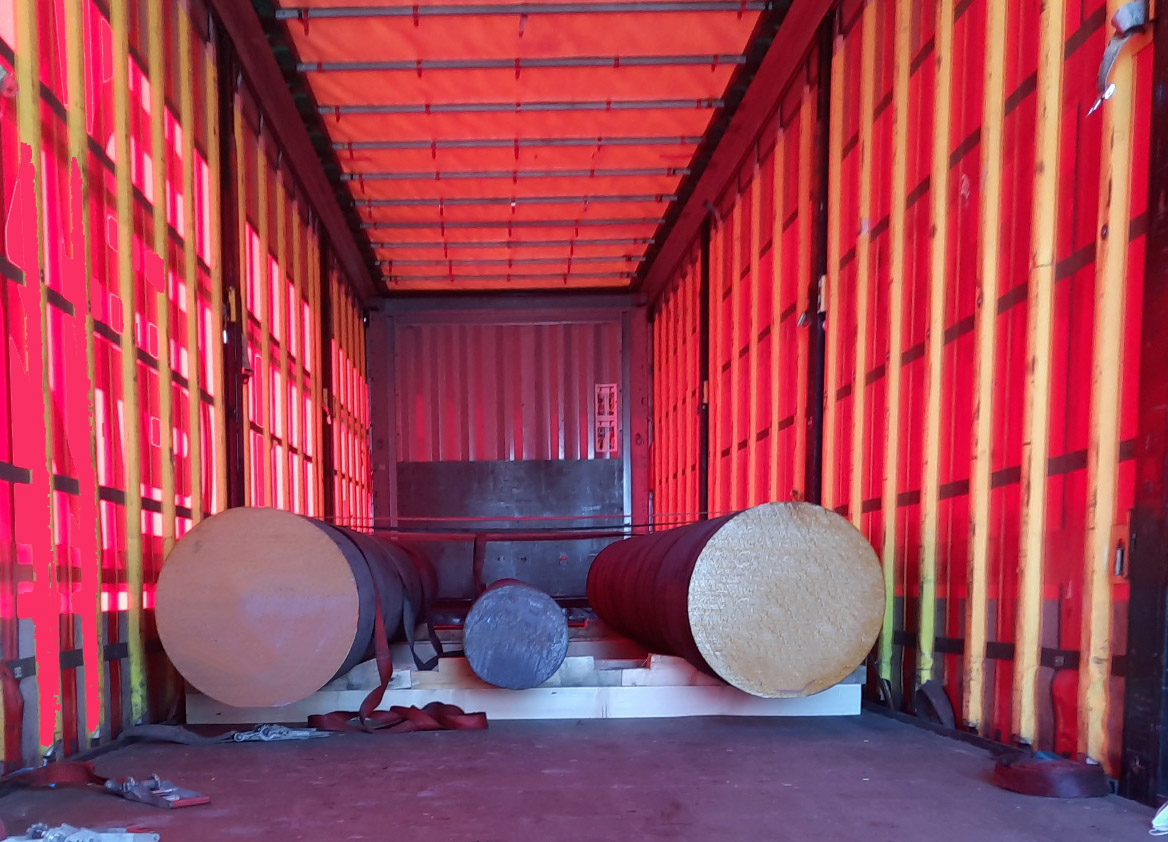
Figure 2 [Raymond Lausberg]
This photo shows that the belts go nowhere near the smaller round bar. It also helps us to clarify the issue of load distribution. The overall center of gravity of the load is at the back third of the area between the first and second stanchions. Depending on the type of the vehicle, this may just be okay, but it is probable that the load should be placed a little further to the rear. But it appears not to be a major issue.
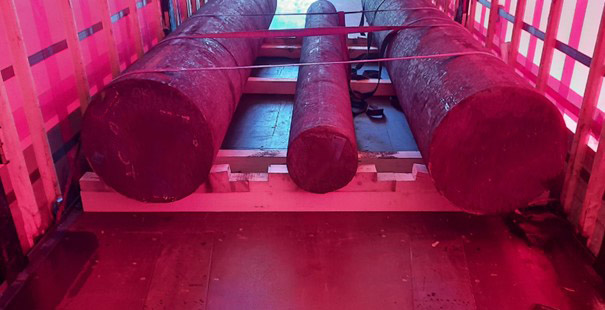
Figure 3 [Raymond Lausberg]
This photo calls to mind a tried and trusted rule of load securing: “Small feet, narrow and tall, more often than not lead to a fall.” In this case, we are looking at dunnage, not feet, but exactly the same principle applies. In this photo, we can see a total of 5 pieces of dunnage. Wedges have been fixed to the first and last of these in order to secure the load to the sides. As required by this method of securing, the round bar is “floating” above the dunnage and is supported only by the wedges on each side. So far so good. As a result, the whole weight of the round bars is concentrated on two pieces of dunnage (the ones with the wedges) and the remaining pieces of dunnage make a good impression, but no more than that, because they are not in contact with the load in any way. We do not know how the loading bed reacted to this state of affairs, but we fear that these localized line loads will damage it. But the point that we really want to stress here is that this “tall” dunnage is liable to tip during braking or when the vehicle pulls away on a hill. And if it does tip, the load will no longer be secured to the sides and the pre-tensioning force of the tie-down lashings will be lost.
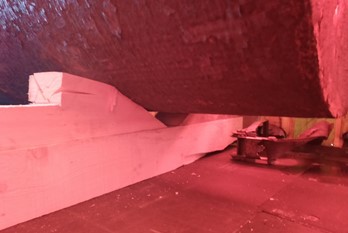
Figure 4 [Raymond Lausberg]
Key points about securing using wedges:
- Wedges represent a good securing method, as they provide a tight fit proportional to the height of the tipping edge. The extent of this proportional tight fit is shown by the sine function in the diagram and table below.
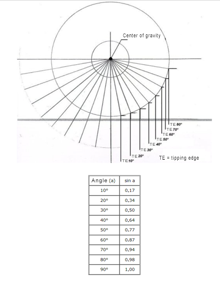
Diagram/Table 1 [GDV] - It is a fundamental prerequisite for this method of securing that 1) the wedges are sufficiently robust and 2) they have not already been deformed by the weight of the load.
- There must never be any risk of tipping. This is achieved by making the dunnage far wider.
- The use of anti-slip material is not forbidden in this scenario, including between the dunnage and the loading surface. Heavy-duty anti-slip material should be used between the load and the lumber as high line loads are to be expected here.
- In reality this means: If anti-slip material is not used in all appropriate places, the high level of friction offered by the anti-slip material cannot be taken for calculating the securing measures required:.
How to secure the load properly:
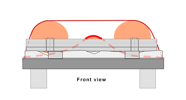
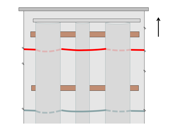
Securing of the load to the sides can be achieved by placing the load on wedge-shaped supports. In this example, the way in which the load is secured to the front falls somewhat short of what is needed – which is putting it mildly. We would build a barrier consisting of two or three pieces of squared lumber in front of the round bars. These would be raised using short lengths of squared lumber to ensure that the barrier covers all three round bars at the same time.
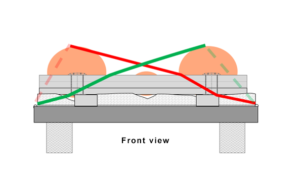
Diagram 2 [GDV]
The barrier is restrained using two belts arranged as loop lashings. It is important that the belts are of the same length and that they are protected against sharp edges and abrasive surfaces. Protective sleeves are likely to be the equipment of choice here. Each belt provides a securing force of 4000 daN (less any loss as a result of the angles involved). This results in 8000 daN less, for example, 2000 daN to account for the angles, leaving 6000 daN of actual securing force. If the load is resting on anti-slip material throughout, 4800 daN of securing force is needed to the front, and this has been achieved with plenty to spare in the example described above.
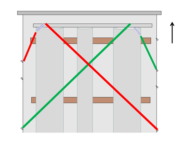
Diagram 3 [GDV]
It is important that each of the round bars is subject to the minimum securing force (tie-down lashing). This requires a total of four tie-down lashings: two for the large round bars on the outside and two for the small round bar in the middle. This also takes care of securing the load to the rear, since the friction acts in all directions. At this point, we should mention that all of the belts were completely loose when this load was inspected. This may have been the result of the load working its way into the wood, and thus reducing the total circumference of the load. The load-bearing surfaces must be of a sufficient size and the belts must be protected from the rough surfaces of the round bars, and then this load can be transported safely.
Diagrams 4, 5 [GDV]
Your load securing columnists wish you a relaxing, safe and secure advent season!
Back to beginning