
| Photo of the month – August 2022 |
[German version] |
So they all rolled over and…
Not steel again, some readers will be saying to themselves. That’s right, it’s steel again. But it’s just such a wonderfully versatile material that it is always opening up new perspectives.
The title of today’s Photo of the Month has been borrowed from the English nursery rhyme, for which we crave your indulgence. But rolls of cargo lying with their winding axis crosswise to the direction of travel just wakens childhood memories for us.
So what is the problem with this loading method? You’ve got it! If it comes to the worst, the only friction acting on the load is rolling friction, which we ignore when doing the load securing calculations. This means that we have to do the calculations using 80 % of the weight of the load in the longitudinal direction, and this needs to be fully accounted for by the securing measures. As if that were not enough, the same applies opposite to the direction of travel. The 50 % we would usually need to the rear will generally be accounted for by friction and the securing measures that we need for securing the load to the sides. But if the load is able to roll, there is no friction and we have to explicitly address the issue of securing the load to the rear.
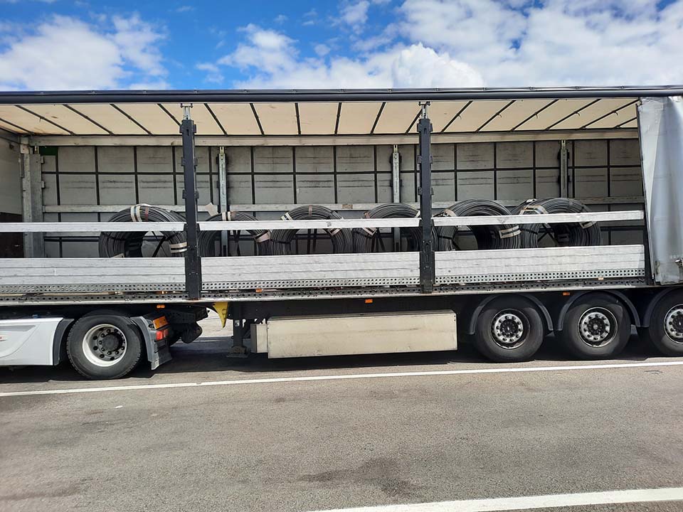
Figure 1 [Raymond Lausberg]
So this is the scenario: Wire rod coils are lying on a curtainsider trailer with their winding axis perpendicular to the direction of travel. At first glance, the load distribution appears to be okay. The overall center of gravity of the load is approx. 0.8 to 1 meter in front of the first axle unit. Without detailed knowledge of the load distribution curve, it is not worth looking at this aspect any more closely (we are not nit-pickers, although we sometimes appear to have this reputation).
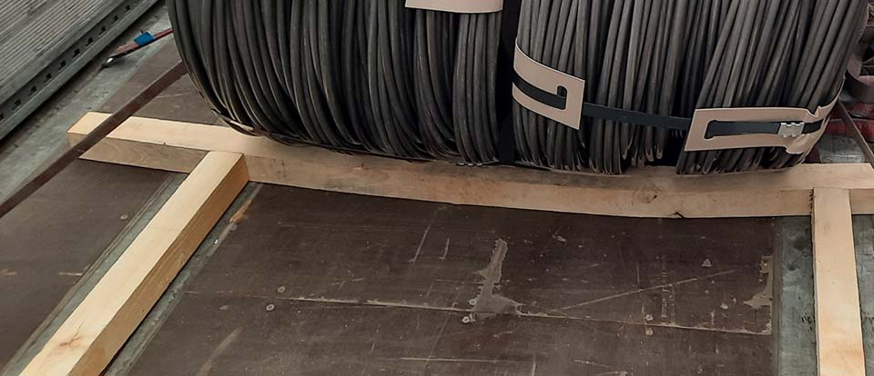
Figure 2 [Raymond Lausberg]
Clearly, those responsible have grasped, or at least been dimly aware of, the importance of securing the load to the front. They decided to use a tight fit to deal with this important aspect. Or perhaps we should say that they thought about using a tight fit.
What measures were taken?
- Three heavy lengths of lumber were placed on the loading bed, two lengthwise and one crosswise. And that was it.
- This is a good loading aid, as the loader can easily place the load units up against this “construction”.
- But that’s all!
- If wedges are to be used to prevent cylindrical cargoes from rolling longitudinally, the height of the wedges should be at least 1/6 of the diameter of the cylindrical cargo.
- The force must then be well distributed across the end wall, and not applied at a few points as in this example.
- Furthermore, the load must also be prevented from simply rolling over the equipment used.
- The wedge should be as wide as possible in order to protect the cargo (an attempt was made to do this here, with the lumber laid across the entire width of the vehicle).
- And if wood is to be used, then it should be wood that is up to the job. In this case, the wood used was of inferior quality, with knots where the wood probably failed (cracked) during loading.
- Oh yes, before we forget: Every coil would have to be restrained like this with wooden wedges!
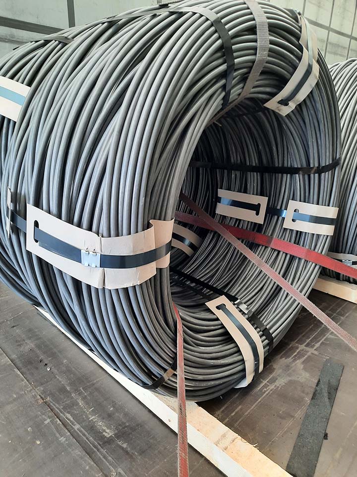
Figure 3 [Raymond Lausberg]
We couldn’t quite figure out the way in which the load was secured. In Figure 3, we can see the last row of coils in the load.
- The first belt in the foreground is a sort of loop lashing to prevent the load moving forward. That’s fine. You can do it that way, although we would have taken the belt far further back to decisively counteract any forward movement (rolling direction). We would also have avoided such a tired-looking specimen as this one (if it is not already fit to be scrapped, it will be shortly).
- The second belt, which rises a little into the eye of the coil, is what is known as a “silly loop”. Its function is to bundle together the two coils that have been loaded next to each other. It does not perform a proper securing function, because it would simply slip when a load is applied. If the coils are to be bundled during loading, this is better done with a bundling belt. This is taken through the eye of the coil, threaded into itself and tightened.
- The third belt (dark red) is a loop lashing to the front, to restrain the load against movement to the rear.
How to secure the load properly:
So how would we secure the load?
- You can use lumber as in the example, but you don’t have to. If you choose to do so, the height of the wedge must be at least 1/8 of the outside diameter of the coils (preferably a good bit more). In this case, it would have been possible to use a 15 x 15 cm piece of squared lumber that has been heavily chamfered on one side to protect the load. The force can be transmitted forward to the end wall, where it has to be effectively distributed. Important! What kind of end wall are we dealing with?
- We would place the load on anti-slip mats anyway and use squared lumber dunnage when loading. This is for reasons of health and safety and they would not be used to secure the load. The anti-slip mats provide good securing to the sides.
- We would use loop lashings to the front and rear. Let’s assume a full load. Given a weight of 24 tonnes, we have to take up 19,200 daN to the front. To do this, we take six loop lashings to prevent the load from moving forward and pass the ends of the belts a long way back or forward in order to obtain the most favorable angles possible.
- To restrain the load to the rear, we take four belts and proceed as above, also trying to achieve favorable (shallow) angles.
- We could rely on the anti-slip mats to prevent the load from moving to the sides, but we do not have the minimum securing force to do this, namely one tie-down lashing per pair of coils.
- Since this tie-down lashing would have very shallow angles, we shall instead use three more loop lashings per side. We shall always use one loop lashing for two pairs of coils and secure them to one side. To do this, we pass the belt through one coil eye and back through the other coil eye (in the form of a “U”). This requires another three loop lashings per side, but secures the load excellently.
- Yes, it’s an elaborate way of securing the load, using 16 belts and anti-slip material. But it is also a load that has been loaded in the direction in which it is liable to roll, where friction only comes to our aid for securing to the sides. We wouldn’t actually need the anti-slip materials, because we are using loop lashings to provide plenty of securing force, but we have chosen to be on the safe side because it is always better to be safe than sorry and friction costs (virtually) nothing.
Your load securing columnists wish you a relaxing summer.
Back to beginning