
| Photo of the month – April 2022 |
[German version] |
Question: Is this okay?
Let’s break down this question into a number of steps.
- What levels of friction are involved?
- What is the packaging like?
- Is the load distributed properly?
- Are elements of the vehicle used to help secure the load and are they capable of meeting the demands placed on them?
- Are the load-securing measures adequate?
- What needs to be improved in respect of all these different aspects?
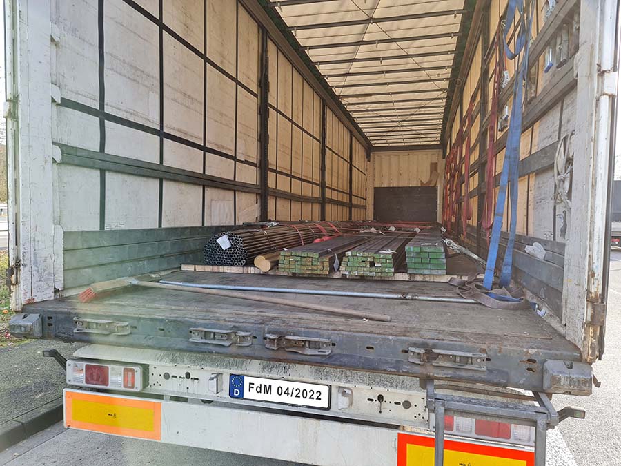
Figure 1 [Wolfgang Jaspers]
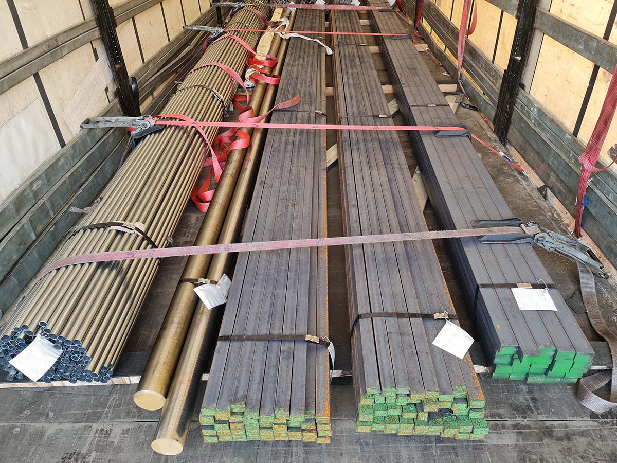
Figure 2 [Wolfgang Jaspers]
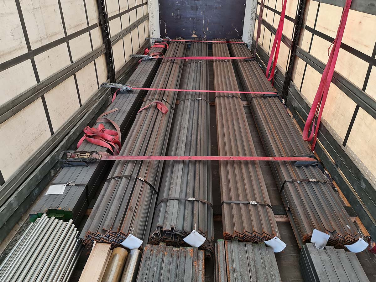
Figure 3 [Wolfgang Jaspers]
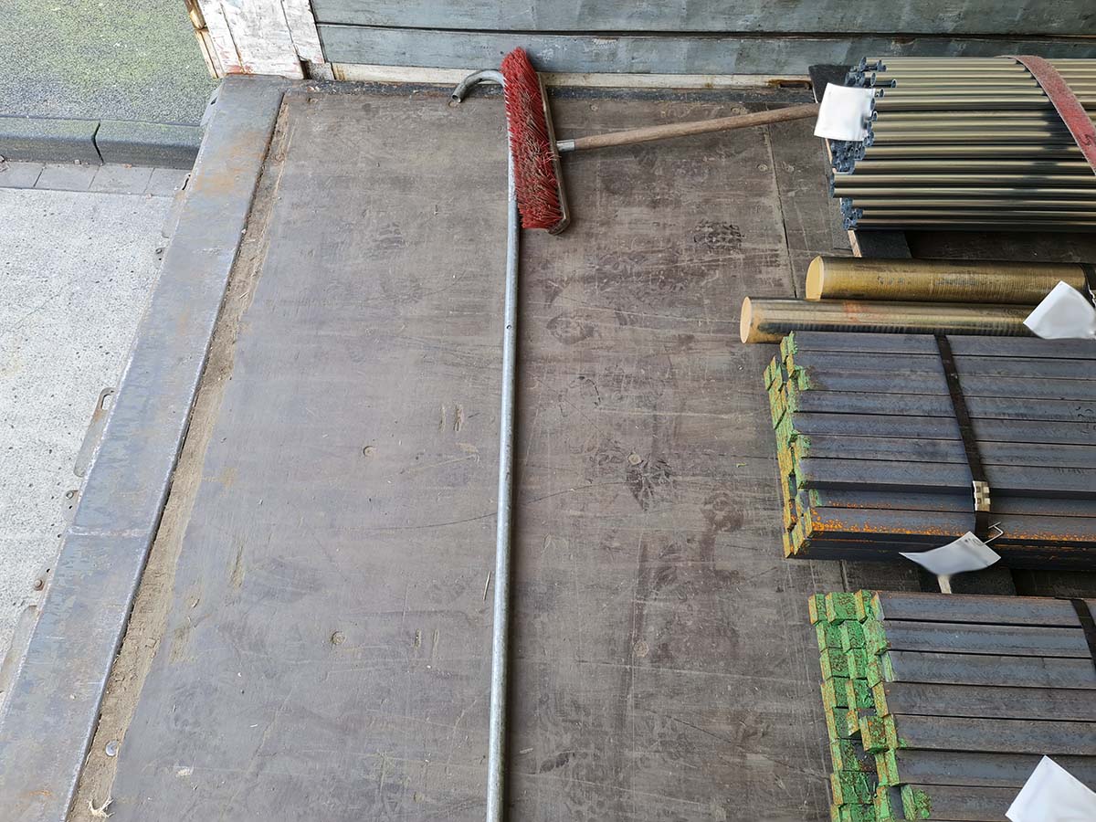
Figure 4 [Wolfgang Jaspers]
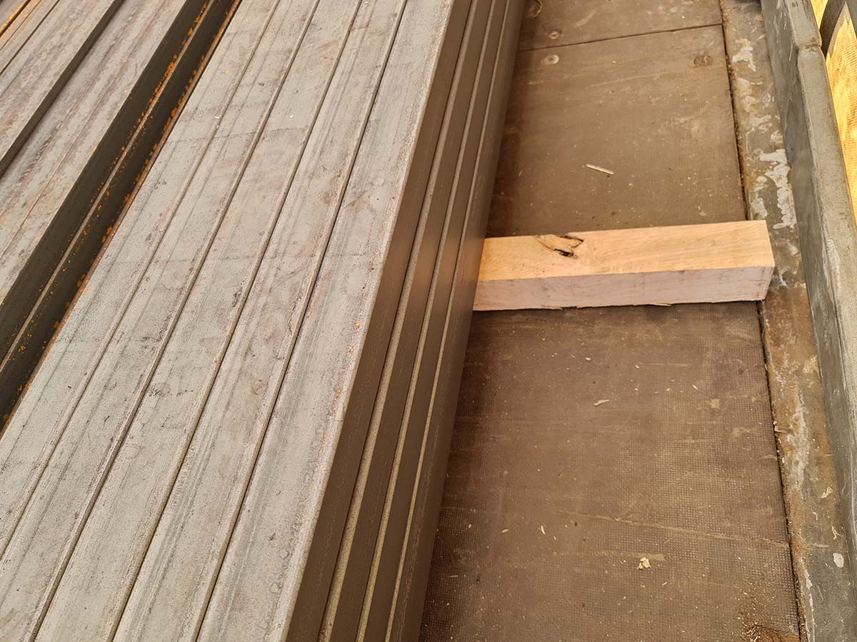
Figure 5 [Wolfgang Jaspers]
Re. 1.
From the very first photo, we can see, or can at least guess that anti-slip mats have been used. Figure 2. confirms that anti-slip mats have indeed been used, at least on top of the wooden dunnage. Anti-slip mats under the dunnage are just as important, as the friction has to be able to propagate systematically right down to the loading surface. And here we see gaps in the friction chain. Only when there is an unbroken friction bond between the load and the loading surface are we able to actually take the high level of friction provided by the anti-slip material into account. By the time we get to Figure 5, we can see that one piece of dunnage was missed out when the anti-slip mats were distributed. That's a pity! What coefficient of friction can we use? We always have to use the lowest value present in a stack or section. This has nothing to do with nit-picking: It is a question of safety and responsible behavior, as we cannot gage the effect friction will have when the load is placed under stress.
Re. 2.
What is the packaging like?
The steel has been bundled to form load units using steel straps. This is a good way of keeping the bundles together laterally, but it cannot reliably prevent individual elements of the load from slipping out lengthwise. Consequently, the way in which the packages are loaded and secured must ensure that individual elements of the load cannot escape from the bundles.
Re. 3.
Is the load distributed properly?
There is a tight fit to the end wall. The load is distributed evenly and there is a gap of more than one meter between the end of the load and the rear of the vehicle. With the load distributed in this way, the drive axle of the tractor unit will be overloaded if the trailer has been loaded to its full capacity. The load should have been distributed asymmetrically to shift the overall center of gravity further towards the rear. On most trailers, the load application point is approx. 0.8 to 1 meter in front of the hub of the first axle assembly. The load distribution curve, which all manufacturers will supply on request, describes in detail exactly where the overall center of gravity of the load has to act.
Re. 4.
One element of the vehicle is used to help secure the load, namely the end wall. The load had been placed as a tight fit to the end wall, but we would have liked to see some arrangement to distribute the forces at the end wall to prevent the wall from being damaged in the event of an incident. Two or three pieces of squared lumber stacked on top of each other would have been sufficient to protect the end wall. Assuming that the end wall complies with the Code XL requirements, it would be able to provide the remaining securing force to the front if the anti-slip mats were used properly.
Re. 5.
Are the load-securing measures adequate? No!
There are gaps between the packages and the angles of the lashing belts are very small (shallow). The gaps between the packages in the load are probably the result of the fact that the vehicle was loaded with a crane. Gaps are left to allow the lifting gear to be removed. These gaps must be filled to provide a tight fit again. This can be done without difficulty while the vehicle is being loaded by using two (or preferably three) pieces of squared lumber placed on end. T-pieces can be made and placed between the load units to eliminate the need to hold the lumber in place. The surfaces indicated with red hatching should be covered with anti-slip material.
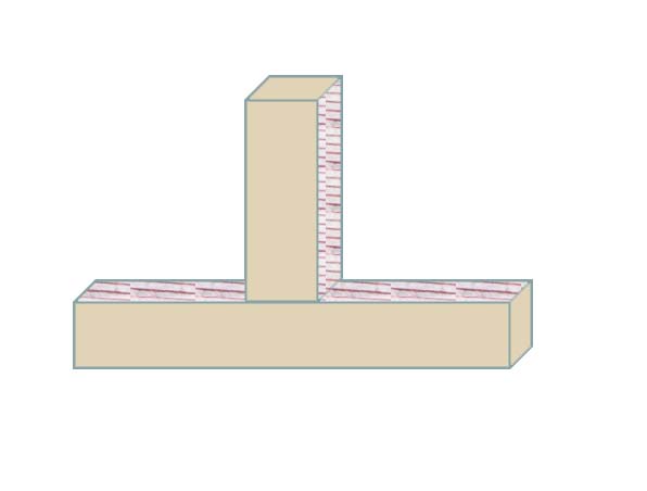
Diagram 1: T-piece [GDV]
Re. 6.
The gaps to the sides of the load units are the biggest problem with this load, as they mean that the tie-down lashings will be useless. The tie-down lashings do not just press the load downwards; they also press it (diagonally) inwards. As a result, the vibrations from the motion of the vehicle will cause the load to move closer together after just a few kilometers. This reduces the overall circumference and the pre-tensioning force vanishes.
The second, bigger problem is the angles of the tie-down lashings. As we said, load distribution was not taken into proper account when this vehicle was loaded. It would therefore be possible to move packages from the front and stack them as a second layer on top of the rear packages. Doing this would considerably improve both the angles and the position of the center of gravity. To allow the friction to be propagated systematically here as well, the second layer must be loaded on sandwich elements, the same as with the first layer.
- Now that we have created the conditions for securing the load laterally as a tight fit, we shall tackle the issue of load distribution. To do this, we shall load load units 4 and 5 centrally at the front of the vehicle. We then place three sandwich elements on top of these and place load units 2 and 3 on top of them.
- We assume that load unit 1 is the heaviest of the load units at the front, so we shall load it next to load unit 8 in the rear load block (to improve load distribution). This means that the two lower load units (8 and 9) are surrounded on each side by the slightly higher units 1 and 10. Sandwich elements are placed on the two load units 8 and 9, and load units 6 and 7 are placed on top of these.
- Squared lumber is stacked between the front and rear load blocks to act as an artificial end wall. A good result can also be achieved by standing two pallets on end and passing several pieces of squared lumber through them. There are no limits to your imagination here. The only important thing is to ensure that there is a tight fit to the end wall.
- The load can now be secured using loop lashings, 3 to each side of each load block. These loop lashings have three functions: 1. they also bundle the load 2. they secure the load to the sides perfectly and 3. they provide the necessary minimum securing force to ensure that the friction can act properly.
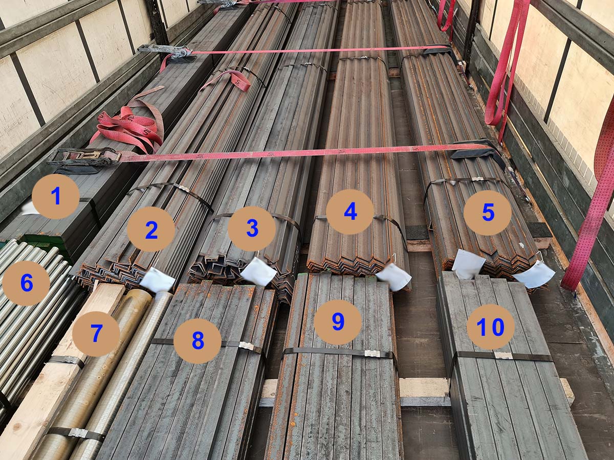
Figure 6 [Wolfgang Jaspers]
Your load securing columnists wish you a safe and secure spring.
Back to beginning