
| Photo of the month – April 2021 |
[German version] |
Torpedo tubes ready to fire? Or perhaps just a good start?
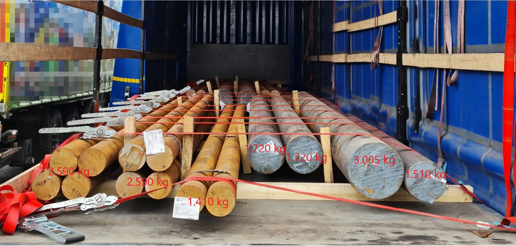
Figure 1 [Wolfgang Jaspers]
To let the cat out of the bag straight away, we’re talking about steel again. To be precise, we are looking at solid round steel bars. The weights of the rear part of the load are shown in the picture. It is not difficult to see that the steel is secured with tie-down lashings and a round turn. The load is divided into two groups. One part of the load is at the front and one at the back. This is to meet the requirements of load distribution.
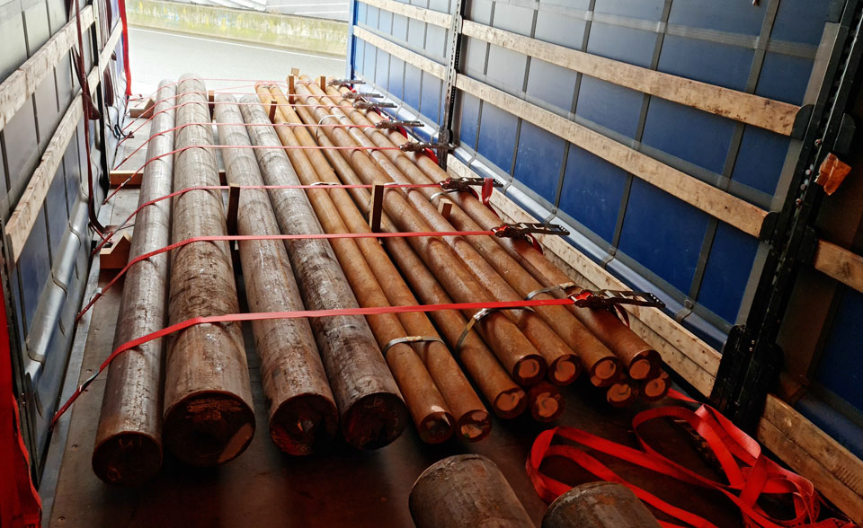
Figure 2 [Wolfgang Jaspers]
The rear part of the load was not loaded as a tight fit to the front. The load was further subdivided by pieces of wood that had been inserted vertically. The belts used were as good as new and they were all equipped with long-lever ratchet handles. They showed a good level of pre-tensioning force. Each of the two parts of the load were resting on three pieces of lumber with a square cross section.
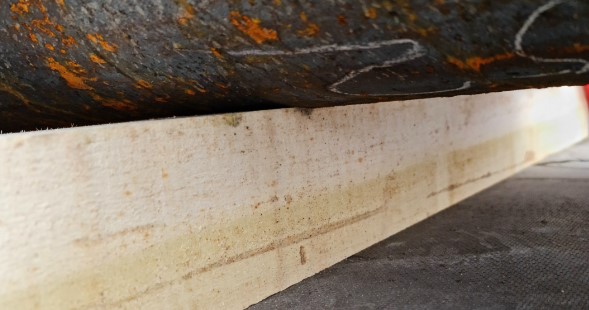
Figure 3 [Wolfgang Jaspers]
The round bars were lying directly on the lumber. Sadly, no anti-slip material whatsoever was used. Furthermore, the dunnage had a square cross-section, which can tend to roll when a load is applied. This is especially important in this example, as the load was secured to the sides with wedges.
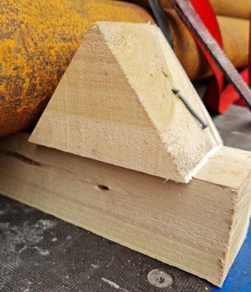
Figure 4 [Wolfgang Jaspers]
In principle, it is a good idea to use wedges for securing purposes, but it is necessary to observe a few basic rules. The wedges have to be cut correctly, which was not the case here. With the wedges shown here, the nails have to be driven into the end grain, which promotes splitting of the wood. It’s not difficult to remember: How would I place a piece of wood on a chopping block if I wanted to split it? That is precisely the wrong way to use it for securing purposes or if you want to nail it. The cutting pattern for pipe wedges … See Diagram 1.
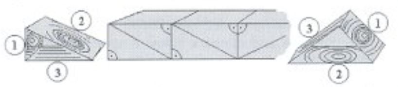
Diagram 1 [TIS]
Wedges must be used in such a way that nails can be driven into the side along which the grain runs (3). Nailing into the end grain (1 or 2) can lead to cracks when driving in the nails or as a result of jolts during transport. Experience shows that the withdrawal resistance of nails in end grain wood is half as much as on the grain side.
If pipe-shaped loads are to be loaded in layers rather than using the “bilge and cantline” method, dual wedges can be used in conjunction with the appropriate intermediate dunnage. This method of securing a load only “pays for itself” if the dual wedges can be used multiple times.
If a piece of square dunnage like this were to roll, the load would immediately lose all securing to the side. But let’s return to the wedges and how they should be nailed. A wedge has been nailed properly if it has one tension nail and two holding nails.
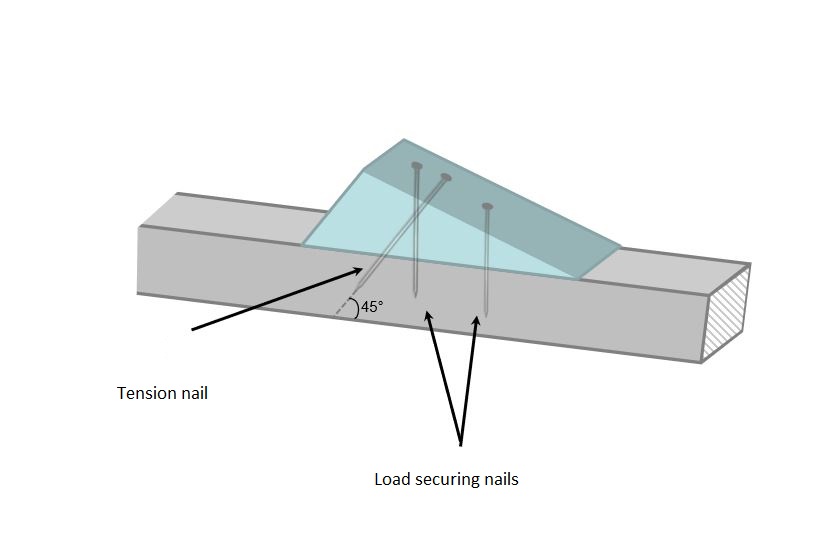
Diagram 2 [TIS]
The nails themselves must have a minimum diameter of 5 mm and must be long enough to penetrate through the wedge by at least 50 mm and penetrate at least 40 mm into the material beneath. No more than the three nails already mentioned may be driven into simple wedges, as any further nails would reduce the strength of the wood and there would be a risk of the wood splitting. Additional nails can be driven into wedges of the kind shown in Diagram 3.
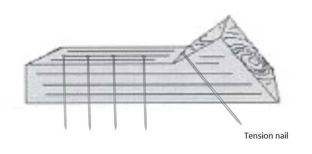
Diagram 3 [TIS]
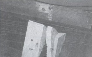
Figure 5 [Wolfgang Jaspers]
If several holding nails are to be driven into the wedge, it is possible to cut the wedge with a “shaft”. Additional holding nails can be driven in here without running the risk of splitting the wood.
Important: Nails must never be driven directly into the loading bed! This does not apply to softwood surfaces, which are sometimes found on lowloaders and other special vehicles.
Our assessment of the nailing of the wedges in this example is as follows:
- The wedge (Figure 5) is cut incorrectly and can therefore not be taken into account when calculating the load-securing measures, as the amount of securing force it provides is unclear.
- Three nails were used, and one of these was no more than a half-hearted attempt.
- We cannot see a tension nail, which would ideally run at an angle of 45° to the cargo to be secured. For our calculations, we shall assume that one of the nails that has been driven in will take over this role.
- Which leaves one load securing nail, which should, if possible, be driven in at an angle of 90° to the dunnage. This nail is assumed to have a securing force of 400 daN (shear or withdrawal force).
Conclusion: A lot of effort to very little effect. There was no lack of awareness of the problems, nor of readiness to do what was required, nor even of the right material. As so often, there was a lack of training and possibly of manual skills.
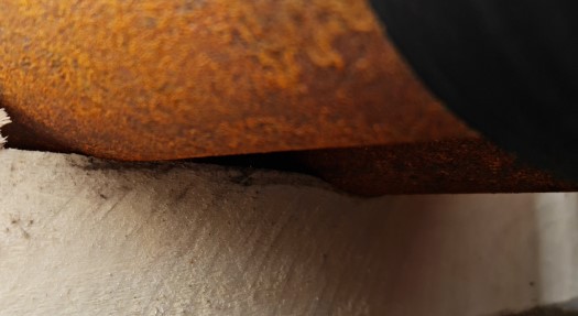
Figure 6 [Wolfgang Jaspers]
And while we are looking at such a multifaceted Photo of the Month, we should perhaps add that the load is crushing the wood in this example. This can change the friction properties of the wood, as the line load results in extremely high pressure that compresses the wood. In particular with hardwoods that are permanently attached to vehicles specially equipped for transporting steel, we often find that with constant use the surface of the wood has become so compressed that it appears to have been polished. Wood such as this has a far lower coefficient of friction. But that is what anti-slip materials are there for.
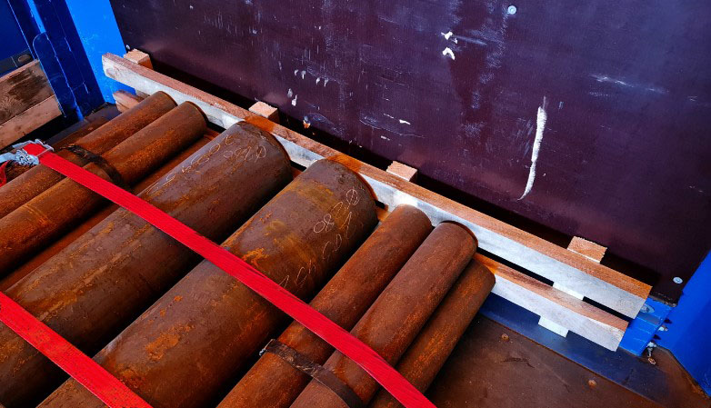
Figure 7 [Wolfgang Jaspers]
Figure 7 takes us on to the exemplary aspects of this attempt to secure the load. We are dealing with a Code XL vehicle, so the end wall provides around 13,500 daN of securing force. The load was distributed, but was then concentrated again, as the vertical pieces of wood exert point loads. But the thickness of the wood and the way in which the tight fit has been achieved is exemplary.
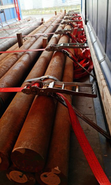
Figure 8 [Wolfgang Jaspers]
Let’s turn our attention to the tie-down lashings. And nothing was done by half measures here. No less than nine tie-down lashings were used on the rear part of the load alone. The long-lever ratchet handles are able to provide 600 daN of pre-tensioning force, and we can say with certainty that this pre-tensioning force was actually present, since the officer carrying out the inspection is one of our two load-securing columnists. So that means everything is fine, doesn’t it? No, of course not, otherwise we wouldn’t have chosen this as our photo of the month.
So where is the problem? Let’s concentrate on the rear part of the load:
Calculation for the rear part of the load:
Weight: 14,545 kg rounded to 14,500 kg x 80 % = 11,600 kg
Friction: µ = 0.3 x 14,500 = 4350 (11,600 – 4350 = 7250)
9 belts x 1200 = 10,800 x 0.3 = 3240 daN (7250 – 3240 = 4010 daN), angles not taken into account.
But this calculation is flawed, because some of the round steel bars are not covered by the belts. The lateral clamping that is a side effect of the tie-down lashings pushes the load together and increases the friction between the elements of the load, but the effect is horizontal and not vertical. Which means that this is not a great deal of use to us in respect of securing the load.
So we have a shortfall of 4010 daN securing force and, as we have already said, we have not even taken the angles into account.
When subjected to a longitudinal load in respect of the truck, the round steel bars can generate a great deal of kinetic energy and transmit this to the front part of the load when they collide with it. The front part of the load is hard up against the end wall and will transmit this energy directly into the end wall, where it is converted into deformation energy. We don’t know whether the end wall would withstand such forces. But the simple fact is that movement such as this simply must not happen.
This “unleashed” kinetic energy is what led us to the title of this month’s photo, even though we also recognized that a good attempt had been made.
But let’s get back to the tie-down lashings:
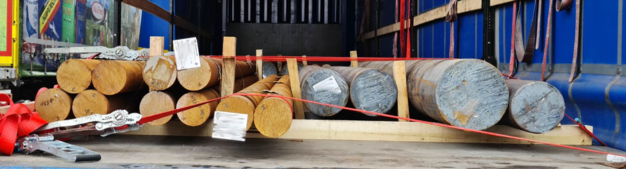
Figure 9 [Wolfgang Jaspers]
A considerable amount of work went into this, but the result was very poor.
- Poor angles
- Many of the elements of the load are not even touched by the tie-down lashings. they are simply clamped in place.
- But plenty of load-securing material was used.
So what would have been needed to secure the rear part of the load?
Four loop lashings to the sides, two to each side.
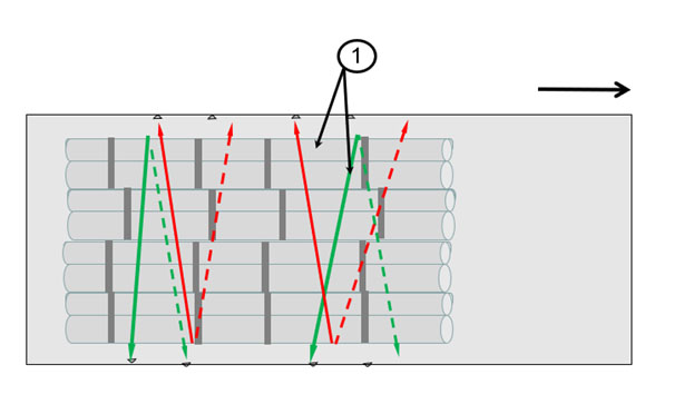
Diagram 4 [TIS]
Diagram 4, point 1: Loop lashings to secure the load to the sides and to apply pre-tensioning force and bundle the load
There are two options for securing the load to the front: 1. An artificial end wall in the form of a lattice, as was used to distribute the load at the end wall, supported by removable stanchions or by two direct lashings in the form of loop lashings.
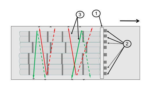
Diagram 5 [TIS]
Diagram 5, point 1: Squared lumber
Diagram 5, point 2: Removable stanchions
Diagram 5, point 3: Loop lashings to secure the load to the sides and to apply pre-tensioning force and bundle the load
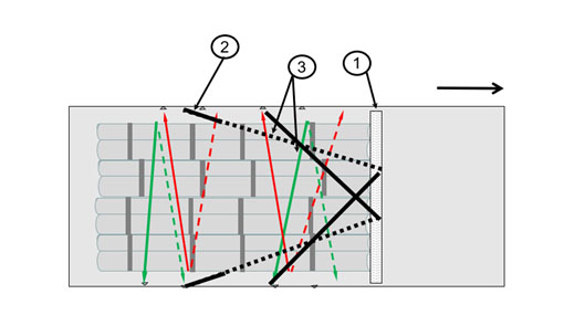
Diagram 6 [TIS]
Diagram 6, point 1: Squared lumber
Diagram 6, point 2: Loop lashings for securing
Diagram 6, point 3: Loop lashings to secure the load to the sides and to apply pre-tensioning force and bundle the load
We shall use anti-slip material (which we recommend in virtually all cases anyway), but this time on both sides of the pieces of lumber that have been inserted vertically as well and between the round steel bars that have not been bundled. In addition, we use two direct lashings to restrain two parts of the load directly.
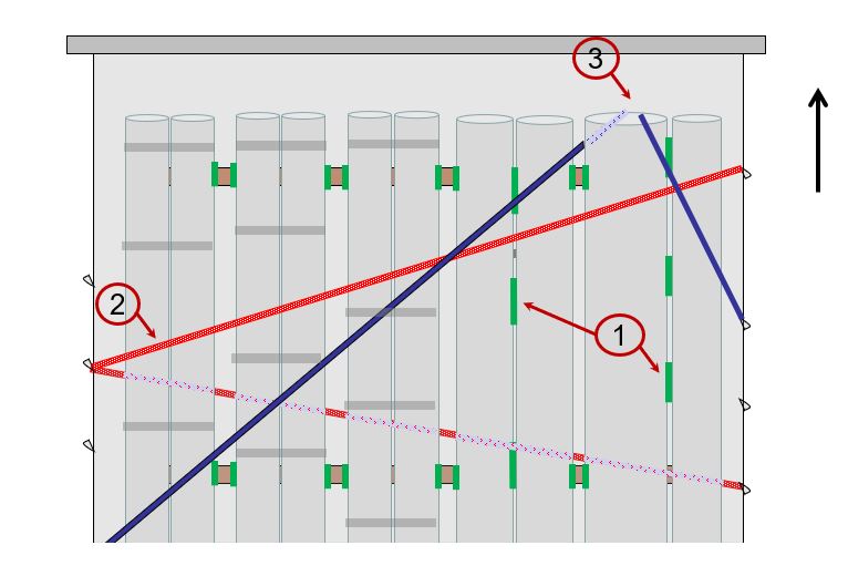
Diagram 7 [TIS]
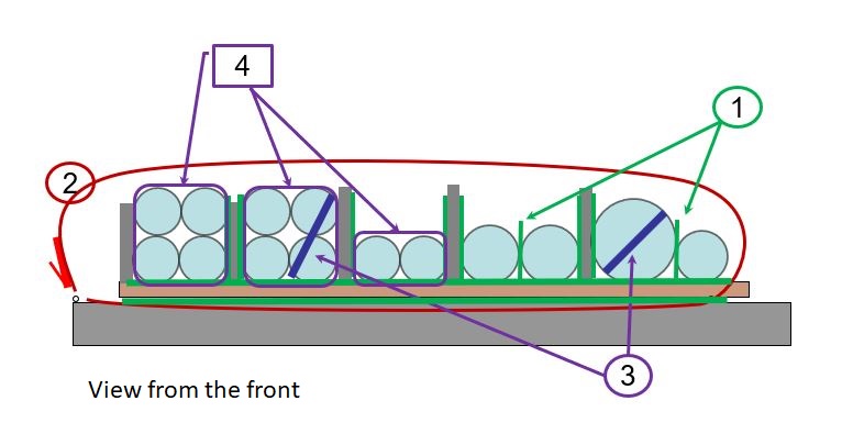
Diagram 8 [TIS]
Diagrams 7 and 8, point 1: Anti-slip material between the parts of the load that have not been bundled
Diagrams 7 and 8, point 2: One of 4 loop lashings to secure the load to the sides and to apply pre-tensioning force and bundle the load
Diagrams 7 and 8, point 3: Loop lashings to secure parts of the load
Diagrams 7 and 8, point 4: Steel straps used for bundling
Now, these parts of the load are subject to friction not only at the bottom, but also at the sides, additionally supported by the loop lashings that push the load together. And because we have restrained two parts of the load against movement TO THE FRONT, the friction to the sides now exerts a securing force. The pre-tensioning force of the loop lashings, which must be high – 600 daN – in this case, generates a total pre-tensioning force of 4800 daN. If we multiply this by the coefficient of friction µ of 0.6, this delivers 2880 daN of securing force. If the rear part of the load is placed on anti-slip material, we still need 2900 daN of securing force. But the friction “to the sides” only delivers 2880 daN, which leaves a shortfall of 20 daN. But because we have used two direct lashings in the form of loop lashings that deliver around 8000 daN of securing force (minus the angles), we also have plenty of securing force in hand with this securing method. We need fewer belts (just six) and we have secured the load well, with plenty in reserve.
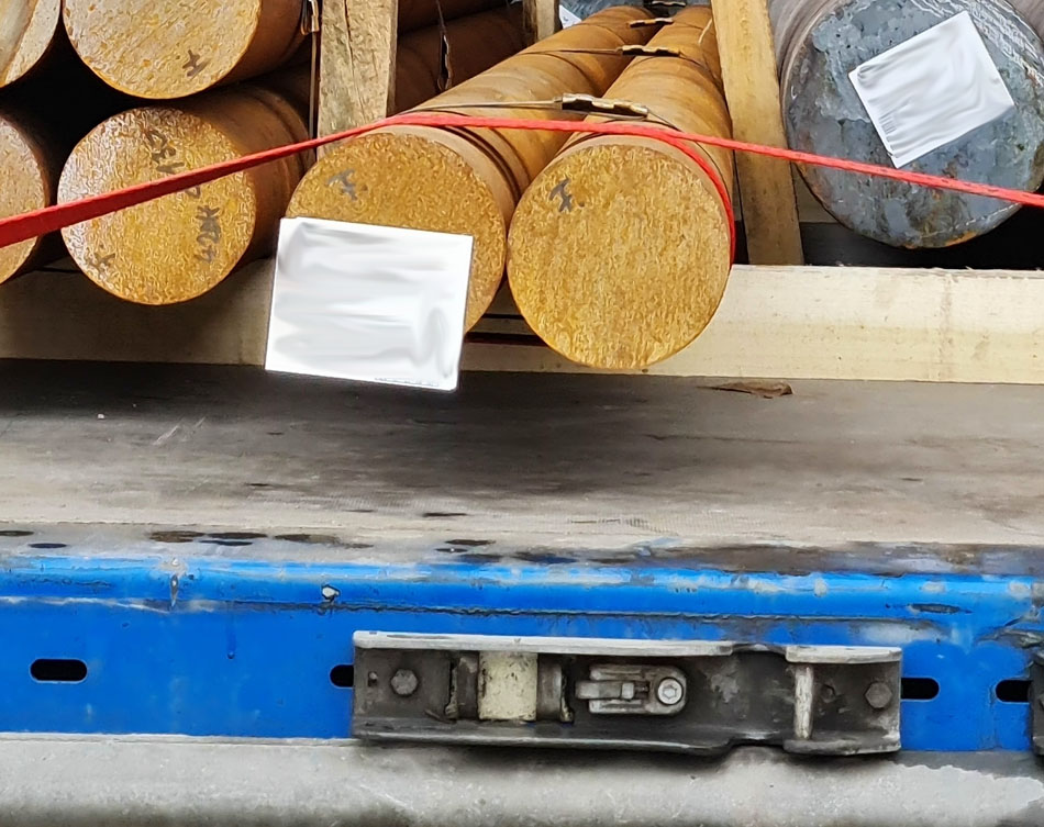
Figure 10 [Wolfgang Jaspers]
Here you can see a detail from Figure 9. This is not simply a tie-down lashing, but rather a round turn. The name comes from the fact that the belt has been taken round the whole load once. Sometimes, this is referred to as a “silly loop”, and the reason it is referred to as “silly” is because a cylindrical load can rotate within the lashing. Now, the two round steel bars that had been captured by this silly loop have been bundled using steel straps. In this exceptional case, this achieves a securing effect as a result of the friction on the corroded steel, but the extent of this securing effect is unknown. We absolutely do not recommend securing a load in this way.
Your load securing columnists hope that you stay healthy and wish you a safe and secure journey!
Back to beginning