
| Photo of the month – July 2020 |
[German version] |
Of cookbooks and burnt offerings
If any of our readers is afraid that our Photo of the Month is about to become a cookery column, we can put their minds at rest. The cookbook refers to a method of ascertaining the effectiveness of direct lashings, and the burnt offering is a load securing point that we will be looking at below.
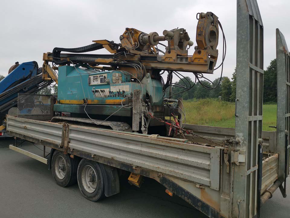
Figure 1 [Wolfgang Jaspers]
This month, we are looking at a drilling rig. According to the identification plate, it weighs 6600 kg and the trailer has a permissible gross weight of 11,000 kg. So far so good. The rig is a self-driving vehicle fitted with rubber tracks. As a rule, rubber tracks are good for load securing, as we can generally assume a high level of friction.
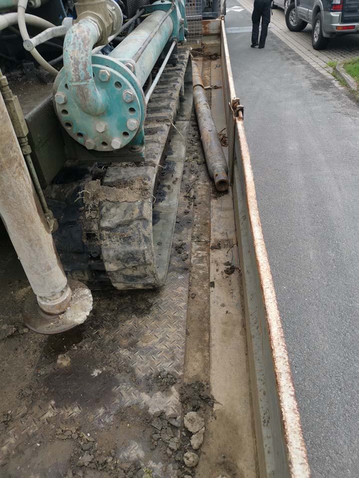
Figure 2 [Wolfgang Jaspers]
But the fact that the tracks and the loading surface were both extremely dirty makes it difficult to assume a good coefficient of friction. In cases like this, we tend to take a very low coefficient of friction, preferably zero. This even though we of course know that there will be a certain amount of friction here, probably with a value for μ somewhere between 0.1 and 0.3. But this is very much a matter of chance, and chance, at least in our books, does not lead to safety. So let us have a look at the load securing arrangements.
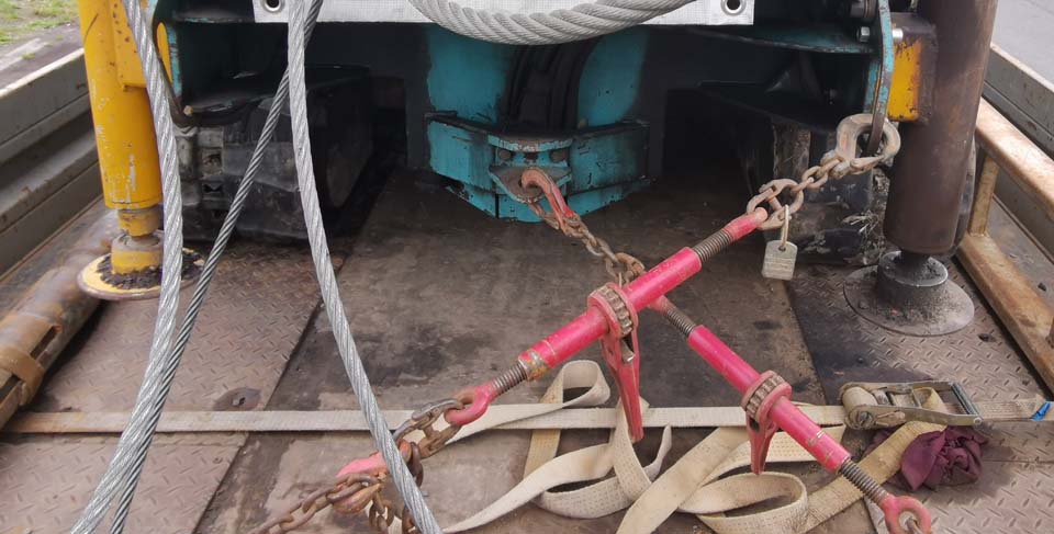
Figure 3 [Wolfgang Jaspers]
Direct lashings were used. Lashings of this kind are often referred to as diagonal lashings because they act diagonally. In fact, diagonal lashings are not a separate securing method. They are simply direct lashings that have a longitudinal and a lateral component (as do almost all direct lashings). They are often attached crosswise due to a lack of space, as in this example. Observant readers will probably already have noticed that different chains have been used in this example and will be asking whether this is appropriate or makes any sense. As a rule, load securing equipment with the same lashing capacity should be used, but if the only items of equipment available have different lashing capacities, they can be used. As in any chain, a load securing arrangement is only as strong as its weakest link. In this case, this may be the load securing point on the trailer or on the load itself.
In virtually all cases, direct lashings that have been attached crosswise make no sense as far as securing the load is concerned. This is because the crosswise arrangement means that the lateral securing effect is generally far greater than the longitudinal securing effect. But because we need a securing force of 0.8 times the weight force in the longitudinal direction and only 0.5 times the weight force laterally, it is obvious that direct lashings attached crosswise usually make little sense. Unfortunately, the available load securing points and, in some cases, the length of the tensioners do not permit any other securing arrangement.
As a rule, direct lashings are attached in such a way that they are symmetrical at the front and back of the load. If they are pre-tensioned to the same level, the only securing effect that acts when no load is applied is the vertical component, which acts as a result of friction. In an ideal situation, the horizontal (longitudinal and lateral) components of the direct lashings cancel each other out in much the same way as with a pair of scales. If a load is applied, the drilling rig will have to move a little (anything from a few millimeters to a few centimeters depending on the elasticity of the securing material). If, for example, the rig slips backwards, the chains at the rear will become slack and only the front chains will be under tension. As the rig continues to slip, the chains stretch and develop their full direct securing force. In the current example, if the rig slips backward a little under load, the asymmetrically attached chains would be tensioned and the rig could possibly twist a little. This is not ideal, and so we recommend that direct lashings should be attached symmetrically where possible.
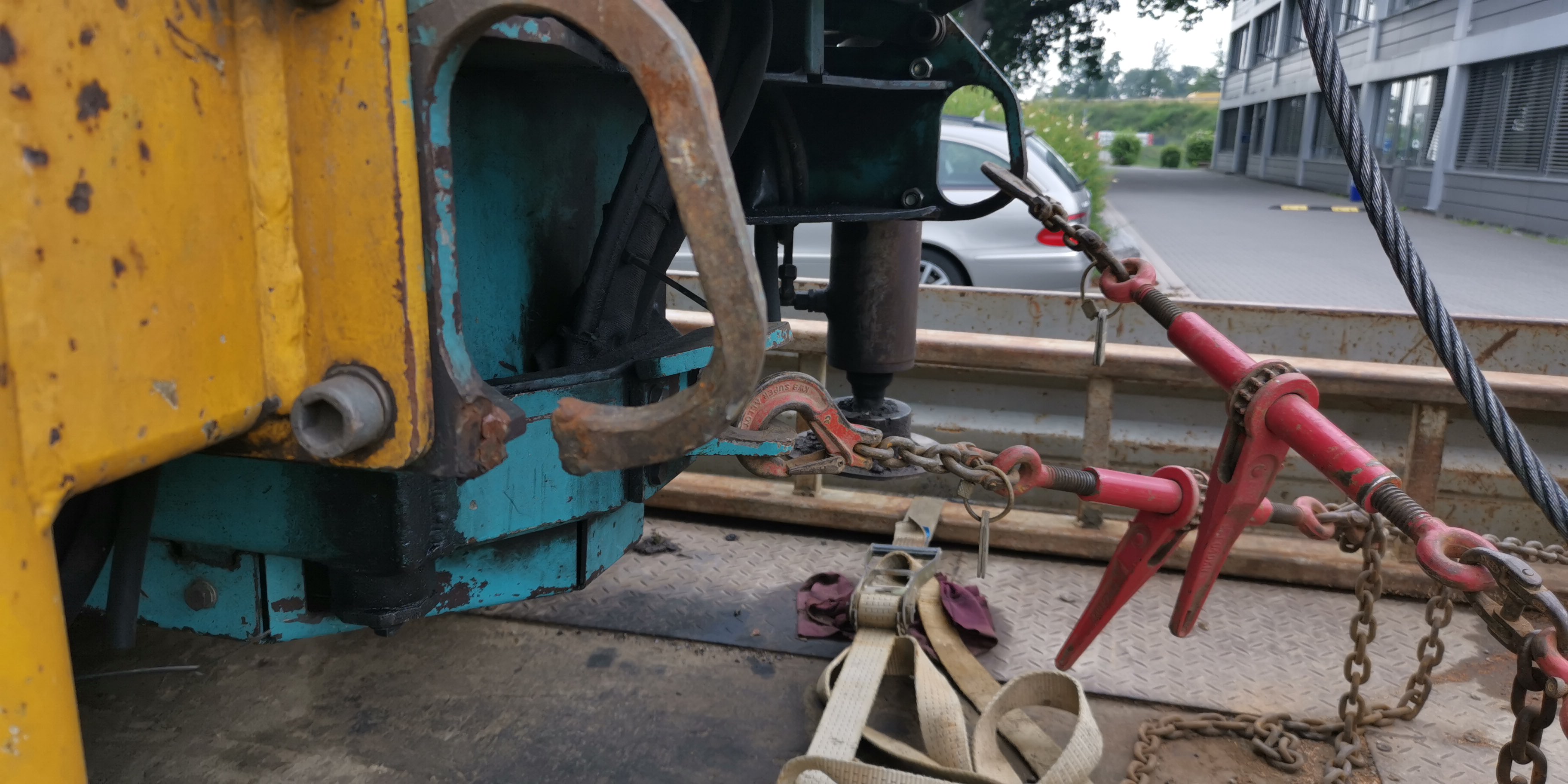
Figure 4 [Wolfgang Jaspers]
This photo reveals why the load securing equipment seen in Figure 3 was arranged so asymmetrically. The load securing point provided to allow symmetrical securing has given up the ghost. Clearly, this load securing point has failed a number of times in the past and was not welded back properly. Instead, we see this rather amateurish burnt offering referred to in our title. This asymmetrical arrangement is not exactly ideal, as the rig could twist when a load is applied, and this should not happen. A further point about these load securing points, if indeed they were provided for the purposes of securing the load: The way in which these securing points have been attached means that they will be subject to strong bending forces, in particular if direct lashings are attached diagonally. It is not possible for forces to be transmitted naturally. Such lashing points should only be subject to longitudinal loads or at least to loads with minimal lateral components. If the tracks of the vehicle had been clean, there would have been no need for any lateral load securing components, as the friction would have been sufficient. A minimal level of securing would still have been needed, but this would have come from the vertical component of the direct lashings. If there are any doubts, we recommend additional tie-down lashings passed directly over the rig.
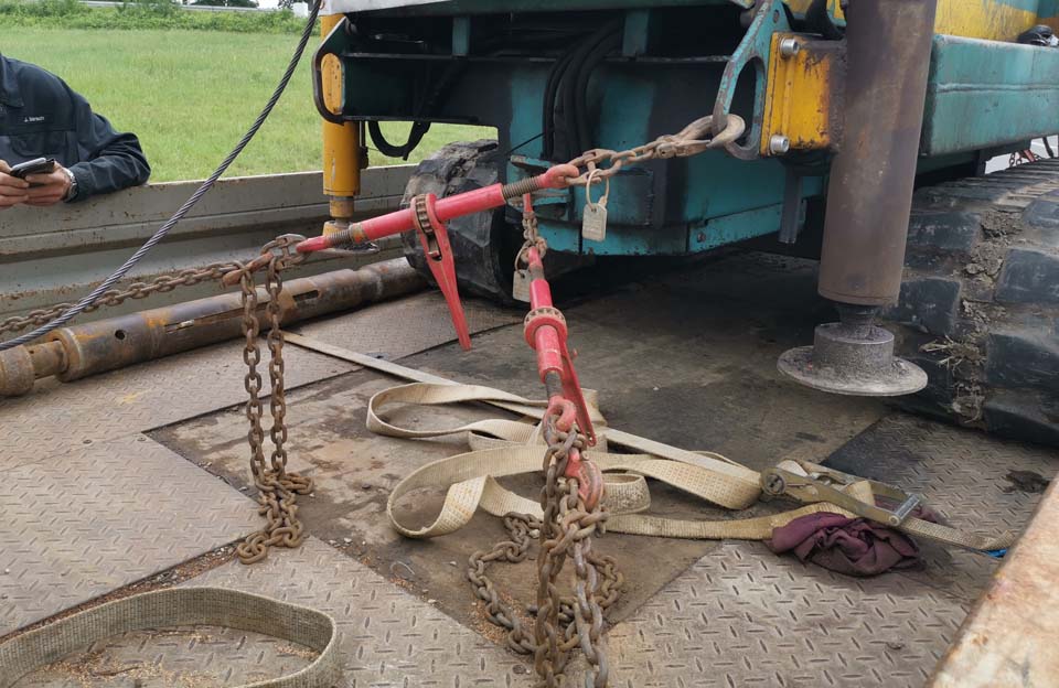
Figure 5 [Wolfgang Jaspers]
Figure 5 shows that the actual direction in which these direct lashings act includes large lateral components. The design of the rig means that they are at a relatively shallow angle, which has a positive impact on the load securing effect. Is there a relatively simple, reliable way of determining the load securing effect?
We refer to our method as our “cookbook”, because it is as reliable as a good recipe if you follow it to the letter.
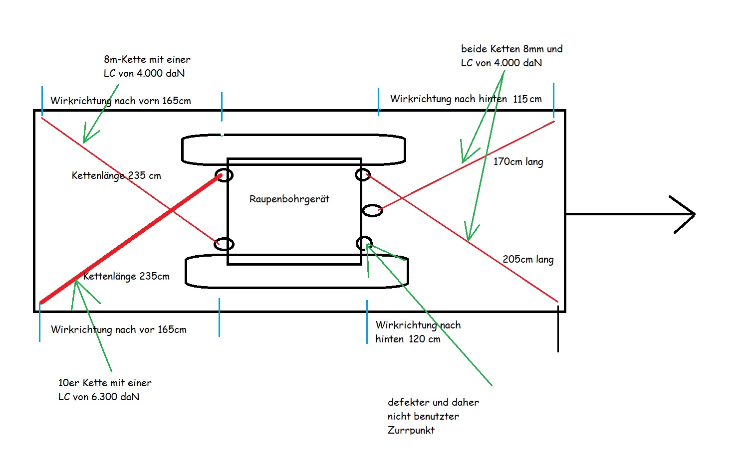
Diagram 1 [Wolfgang Jaspers]
Method:
It is best to use a metal tape measure, because it is not as flexible as a textile tape measure and is thus easier to handle. Measure the effective length of the securing equipment from the point at which the force is transmitted to the vehicle to the load securing point on the load, where the force is transmitted to the structure itself. On the right of the vehicle, this is 235 cm. Now measure the length along the longitudinal axis of the vehicle. Here, this is 165 cm. Now divide the smaller value by the larger value, which will always result in a quotient less than 1. Here, the result is a quotient of 0.70. This means that 70 % of the lashing capacity of the chain is available longitudinally. Of course, the entire securing system must as always be homogeneous, i.e. the load securing points on the load and on the vehicle must be matched to the lashing capacity of the chain. Although the chain we are considering has a lashing capacity of 6300 daN, the lashing capacity on the opposite side is 4000 daN, and so we shall only take a lashing capacity of 4000 daN on this side as well. 4000 × 0.7, i.e. 70 % of the lashing capacity gives 2800 daN of longitudinal securing force. Because the two chains are attached to the chassis of the drilling rig symmetrically, we can double this value. This means that the rig is secured with 5600 daN longitudinally. The weight of the rig is 6600 kg, so we only need 5280 daN of longitudinal securing force. Consequently, the rig is adequately secured longitudinally, without even taking friction into consideration.
And we do not have to take into account that one of the chains has a higher lashing capacity than the other. In most cases, the load securing points mean that we don’t have to deal with this problem, as they are often the weakest links in the securing chain. We always recommend that asymmetrical securing arrangements should be avoided, as things can twist and the weakest load securing equipment can become overloaded when a load is applied.
If it is difficult to measure the lengths of the chains because other parts of the load are in the way, it is sufficient if you measure off the first 100 cm from the load securing point in the effective direction of the load securing equipment. A simple plumb line is then used to drop down to the loading surface from this point. Draw a chalk line at this point and measure the longitudinal distance from the load securing point. This distance will always be less than 1 unless the load securing equipment is parallel with the longitudinal axis and practically lying on the loading surface. The advantage of taking the measurement in this way is that it is possible to read the quotient directly from the tape measure. In our case, the measurement would have been 70 cm, which would mean that, as we determined with the measurements above, the chain acts longitudinally at a ratio of 1 to 0.7. In other words, 70 %!
Your load securing columnists wish you a relaxing, healthy summer!
Back to beginning