
| Photo of the month – July 2019 |
[German version] |
Going underground
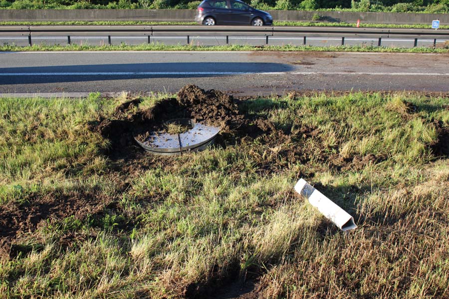
Figure 1 [Niehüser / Zajonc]
As so often, we start this Photo of the Month with the aftermath of an accident.
In this photo, we see a coil of slit strip that has attempted to burrow through the grass and under the road after having fallen from a truck.
If we take a look at the aftermath of this lost load from a distance, Figure 1 gives us a very good idea of exactly what happened: The steel strip coils were loaded on a truck. The truck entered a long right-hand bend to join the motorway. And the driver took the bend at some speed; after all, he was about to join the moving traffic on the motorway.
The load was stacked, and nobody had told it that there was a right-hand bend coming up. So the coils didn't hang on tightly and slipped off the left of the vehicle. Due to the speed, they flew for some distance and buried themselves in the turf.
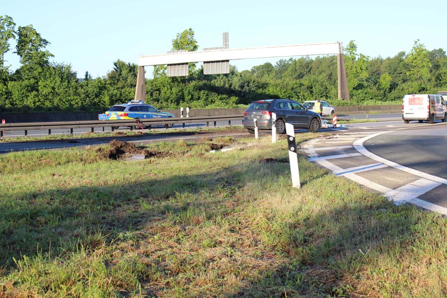
Figure 2 [Niehüser / Zajonc]
In Figure 3, we can see a policeman on the main carriageway shoveling earth back towards the grass verge. So one of the coils must have found its way across the parallel lane, under or over the crash barrier and onto the main carriageway of the motorway. And this is confirmed by the fact that we can see strips of metal on the road in front of the police car.
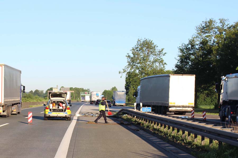
Figure 3 [Niehüser / Zajonc]
And Figure 4 shows us exactly what happened. A bouncer! A nightmare for any goalkeeper: A ball that bounces just in front of the line and changes direction a little in the process. This coil hit the grass, leaving behind a semicircular mark and throwing a lot of soil onto the parallel carriageway, as you can see in Figure 5. It then probably somersaulted, rolled and tumbled its way across the parallel lane and still had enough energy to just about make it across the crash barrier. And it only ran out of steam when it reached the main motorway carriageway.
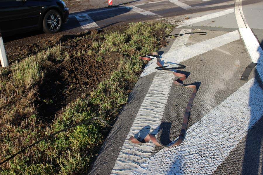
Figure 4 [Niehüser / Zajonc]
Figure 5 gives a very clear impression of the sheer physical force with which the load hit the ground. But it also provides a very good idea of the disastrous consequences this failure to adequately secure the load might have had. But we do not wish to indulge in apocalyptic nightmare scenarios. Instead, we shall content ourselves with analyzing this incident.
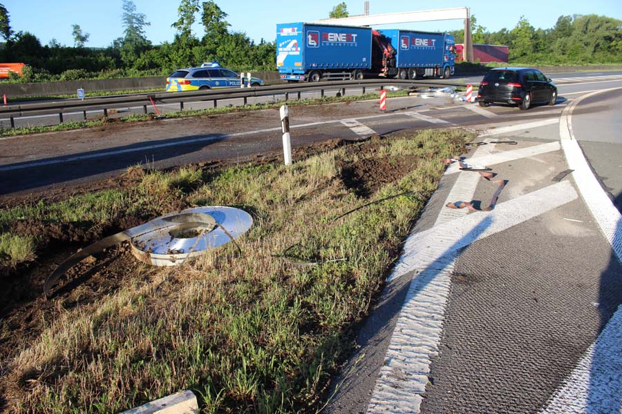
Figure 5 [Niehüser / Zajonc]
Figure 6 shows the soil on the parallel lane and the metal strips decoratively draped between the slip road and the motorway itself. The broom is leaning listlessly against the distance sign and the police officers are discussing all that needs to be done now.
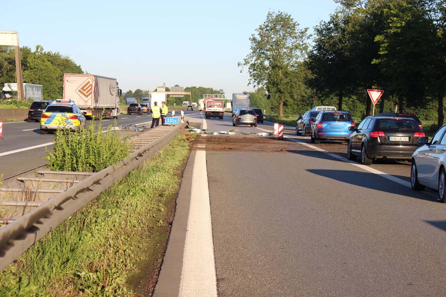
Figure 6 [Niehüser / Zajonc]
Let's turn to the vehicle and have a look at the sidewall (Figure 7). This was bent and damaged by the "escapees", but did not put up any serious resistance to prevent their departure. The thing that transformed this load into potentially fatal projectiles was the lateral acceleration forces, which are sadly all too often underestimated.
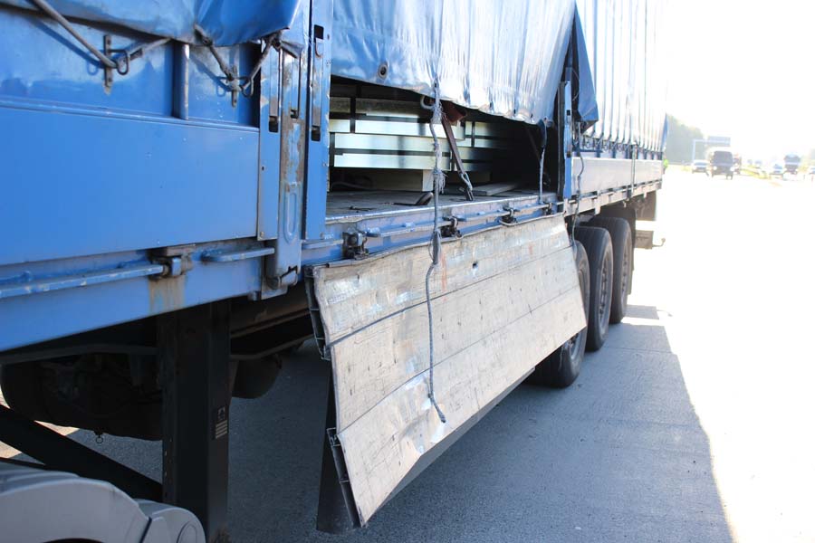
Figure 7 [Niehüser / Zajonc]
In Figure 8, we see four coils of slit strip in a stack, each coil weighing 1156 kg. So what we have here is a stack of steel with a weight of 4.6 tonnes, secured with a single tie-down lashing.
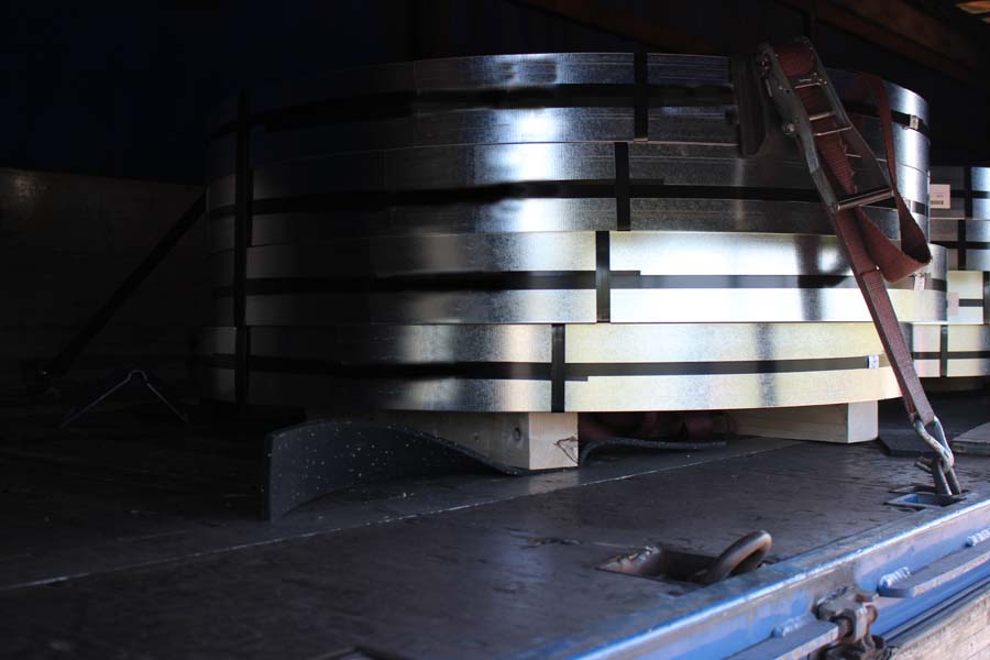
Figure 8 [Niehüser / Zajonc]
Figure 9 gives a clear picture of how the load was actually secured. In order to distribute the load properly, the stacks of steel strip were of different heights. We are unable to work out why lighter load units had been placed close to the axle assemblies (Figure 11) in preference to the heaviest load units. But that is not what we want to talk about today.
As is so often the case, we want to talk about packaging, or more accurately, the formation of load units. The way in which these load units had been formed was pretty lousy: These 4.6-tonnes of slit strip are not resting on stable skids, but have simply been placed on 2 pieces of squared lumber and combined to form a "load unit" with steel straps. Indeed, these four coils have been bundled to form a pseudo load unit with just two steel straps. We often criticize the packaging, for the simple reason that it often represents the root cause of all problems. And that is the case here. If loads are bundled into load units, this suggests that the load can actually be treated as a discrete number of load units. In turn, this means that each entire load unit can at least be secured to the sides by placing anti-slip material under it and applying the minimum securing measures necessary. Consequently, these coils were secured with tie-down lashings and the belts were properly protected from the sharp edges of the steel, which ought to have meant that securing to the sides was taken care of.
Interestingly, Figure 9 suggests that the load units slipped in an arc. It is not clear how to interpret that. But the fact is that the individual coils in the lousy load unit slipped in relation to each other. This meant that the edge protectors were able to slip out, allowing the steel to simply slice through the belts.
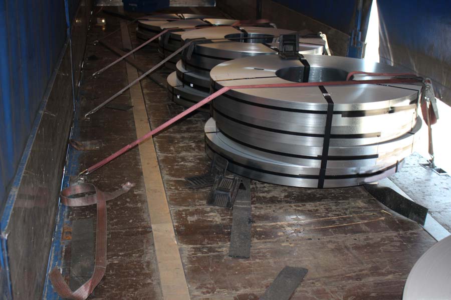
Figure 9 [Niehüser / Zajonc]
Figure 10 shows what we mean by a "lousy load unit". As far as we can see from this picture, the coils are held together only by one steel strap at the front and one steel strap at the back. The steel strap also runs round the squared lumber, which considerably weakens the force holding the coils themselves together. We assume that no anti-slip material had been placed between the coils and the wood. This allows the bottom coil to slip on the wood. And it is almost certain that they did so, as is betrayed by the position of the steel straps, which have slipped to the right in the direction of travel (see Figure 9).
Because the load unit had been constructed so badly, it was subjected to a degree of movement, not just between the coils and the wood, but also between the steel coils themselves. This movement was sufficient to cause the entire load to start to slip. There were a number of consequences:
- The slippage allowed the edge protectors to slip as well, and some of them dropped off, as can be seen in Figure 9.
- Originally, the load units were standing safely on the two strips of anti-slip material, but after slipping, the load units were only half-standing on anti-slip material (see Figure 10).
- This, of course, means that the good level of friction is at least partly lost, and the dynamic slippage begins to pick up speed.
- Figure 9 suggests that the anti-slip material slipped a little with the load, but not fully. Of course, this is not its job.
- Another thing that can be clearly seen in Figure 9 is the effect of the tie-down lashing. The loose stack of slit strip coils initially slipped in stages, with each coil slipping a little further than the one it was resting on until the tie-down lashing was almost vertical, causing it to act, at least partially, as a direct lashing. As a result, the top two coils were unable to slip quite as far as they might otherwise have done. In the case of the lost coils, it is probable that the edge protector on the left also slipped. Alternatively, the coils simply forced their way past the belt, which was undoubtedly facilitated by the fact that they are cylindrical.
- If we assume that the load was only subject to lateral acceleration forces in this bend, i.e. that the vehicle did not brake, the anti-slip material in combination with the tie-down lashing (the minimal required securing measures) should really have been able to restrain the load units.
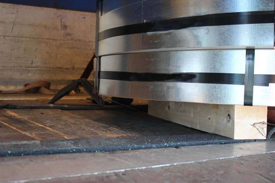
Figure 10 [Niehüser / Zajonc]
Figure 11 clearly shows that the load has slipped in the form of an arc. This might be because load units comprising two, then three and then four coils had been loaded at the back. With each additional coil, the moving mass increased and the ability of the belts to counter this movement decreased proportionally.
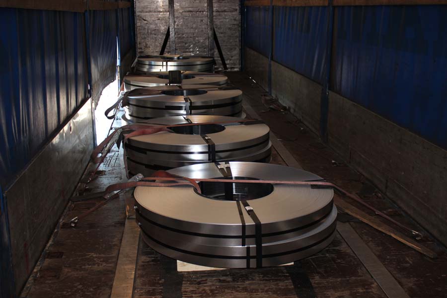
Figure 11 [Niehüser / Zajonc]
We have only included Figure 12 to once again demonstrate how incredibly sharp steel edges can be and to show the damage they can cause.
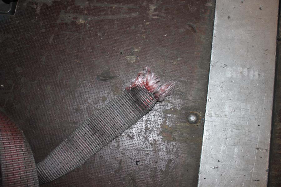
Figure 12 [Niehüser / Zajonc]
Securing the load:
Even though we mentioned that friction should have been able to secure the load to the sides, this cannot and should not obscure the fact that the way in which the load was secured was in fact a disaster. Lashing down 4.6 tonnes of slit strip coils with a single belt is foolhardy. If a weight force of 4600 daN is to be secured using tie-down lashings, 920 daN of securing force is still necessary, provided that the anti-slip mats are placed under the load correctly. Because "only" 60 % of the pre-tensioning force acts via friction (μ = 0.6), 1534 daN of pre-tensioning force is required. For this calculation, the (original) lashing angle of approx. 45° was not taken into account. With luck, 800 daN would have been achieved with one belt, leaving a shortfall of 734 daN.
To put it plainly, this means that these load units, if they had indeed been proper load units, could have been secured with exactly two tie-down lashings per load unit. However, since the load securing arrangements are once again expected to take over the responsibilities of the dreadful packaging, tie-down lashings are not well suited to securing such a load. What is needed here is our ever popular loop lashings. They have to be passed through the coils on both sides and then passed back at an angle. Because we would, of course, put sufficient anti-slip material under the load, it is also possible to attach the belts to a single load-securing point even in the case of weights in excess of 4 tonnes. In our diagram, we have attached the belts to different load securing points for reasons of clarity.
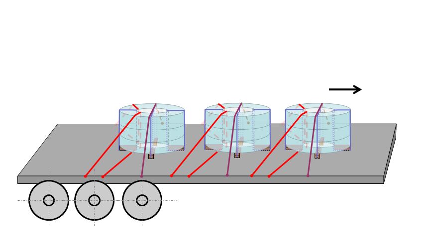
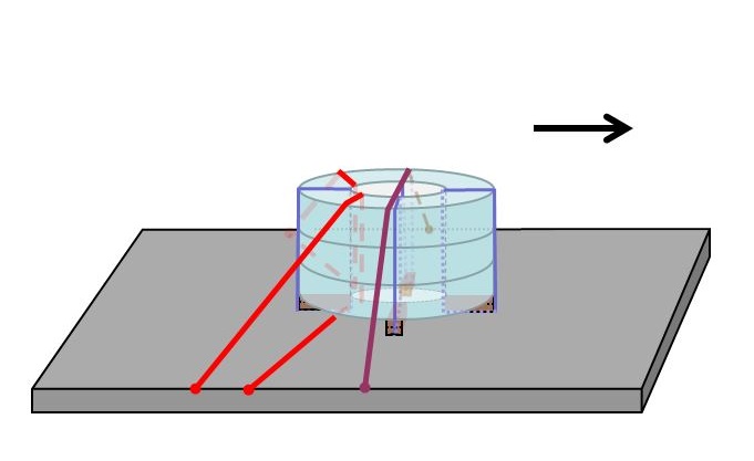
Diagram 1 and 1a [GDV]
Even though the direct lashings also act as tie-down lashings to a certain extent, we recommend a separate tie-down lashing to be on the safe side. After all, we are dealing with steel, and not cartons of crisps.
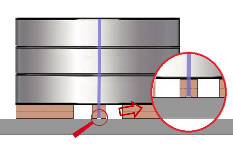
Diagram 2 [GDV]
Packaging / formation of load units:
We would have been far happier if the coils had been combined into a load unit using four steel straps. This would have required 4 pieces of squared lumber as dunnage. These pieces of squared lumber would only have needed to be the same length as the thickness of the coil wall (inner radius to outer radius). A groove for the steel straps is cut into the underside of the squared lumber to protect the straps from being damaged during handling. As far as possible, anti-slip material should be laid under the entire surface of this squared lumber (see diagrams 2 and 3).
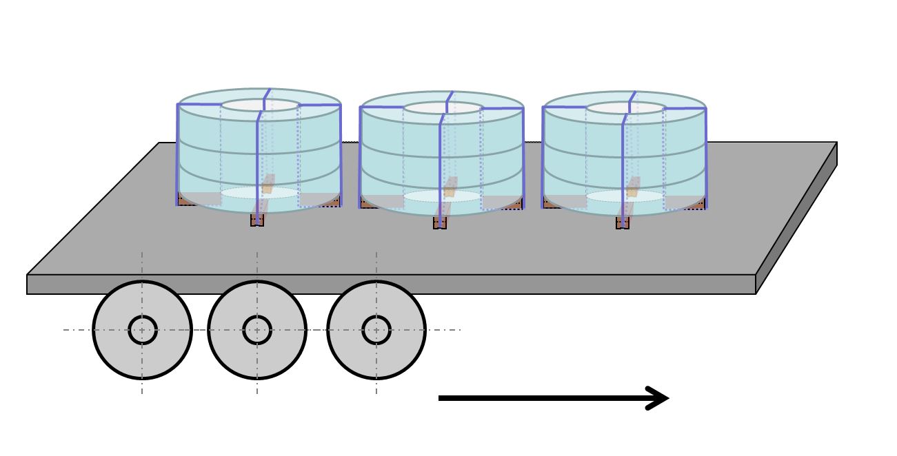
Diagram 3 [GDV]
It would actually be possible to secure a load unit such as this with tie-down lashings, as the packaging method prevents any movement within the load unit itself. But because two belts will need to be used whatever happens, we advocate, as is so often the case, loop lashings as described above. Of course, protecting the belts from the sharp edges of the steel is also of particular importance here. This can be done with edge protectors, protective sleeves or the like.
Your load securing columnists as always wish you a safe and secure journey!
Back to beginning