
| Photo of the month – April 2019 |
[German version] |
A-frame – fail
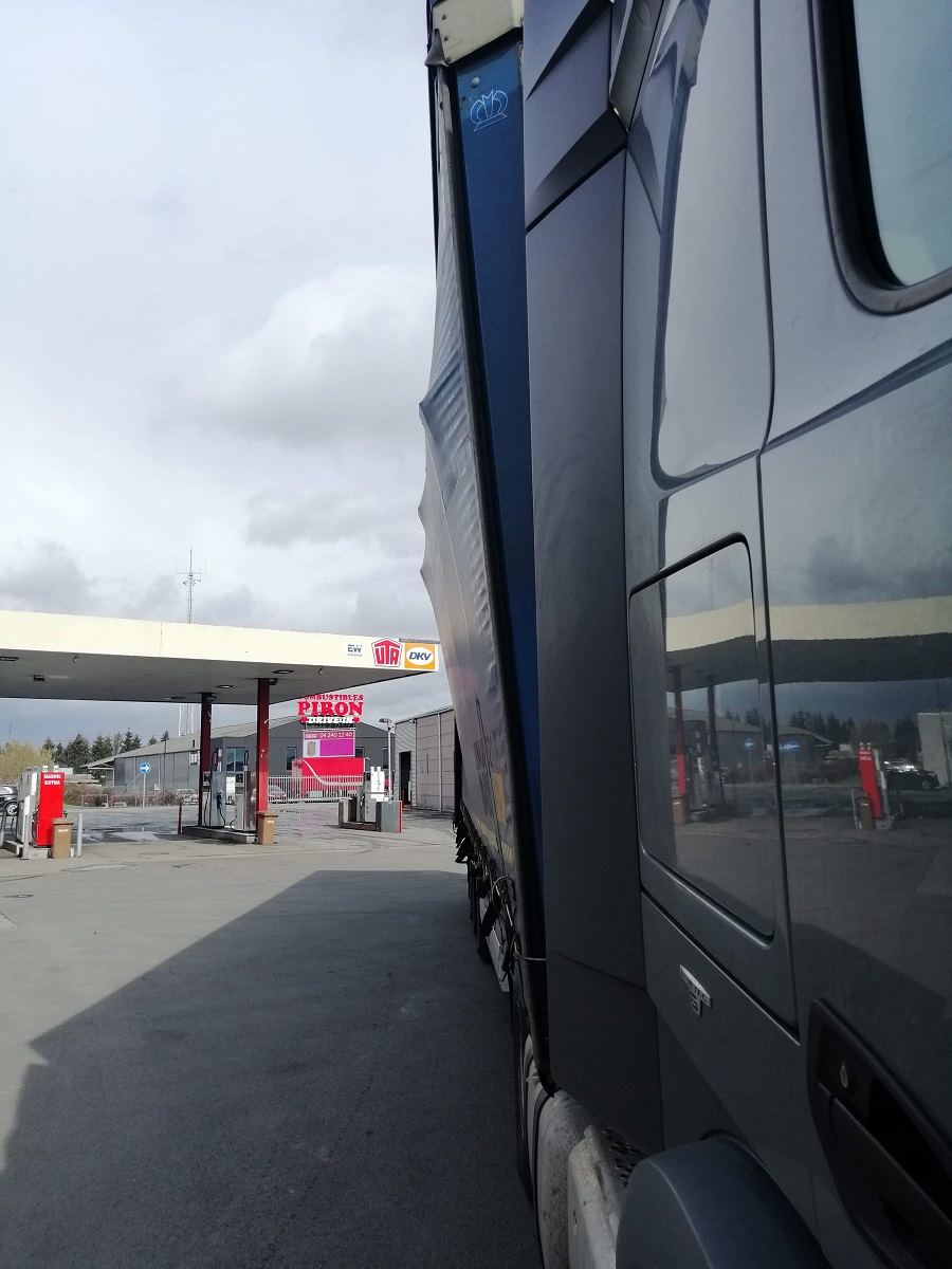
Figure 1 [Raymond Lausberg]
We have the alertness of a Belgian police officer to thank that this vehicle was taken off the roads. The bulges on the right of the vehicle were too prominent to allow it to continue on its way. Such a significant increase in the vehicle's clearance profile indicated something rather more than the load being placed and packed "just" a little awkwardly.
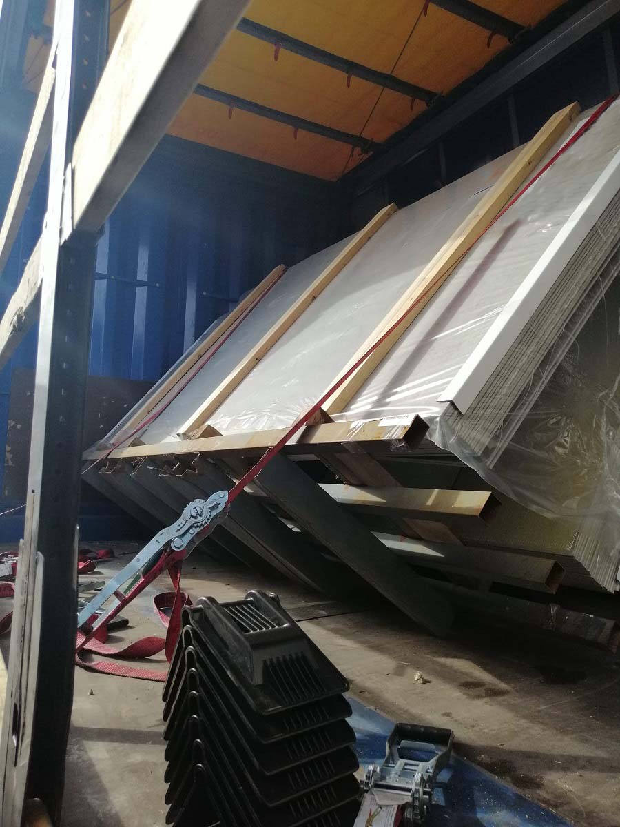
Figure 2 [Raymond Lausberg]
And we shall let the cat out of the bag and enlighten our readers without delay. The load comprised A-frames carrying board material weighing an average of 3 tonnes. As Figure 2 shows rather impressively, the first two A-frames, which were loaded as a pair at the front, shifted slightly to the right. Even though they were "secured" with tie-down lashings, they tipped into the tarpaulin on the right side of the vehicle.
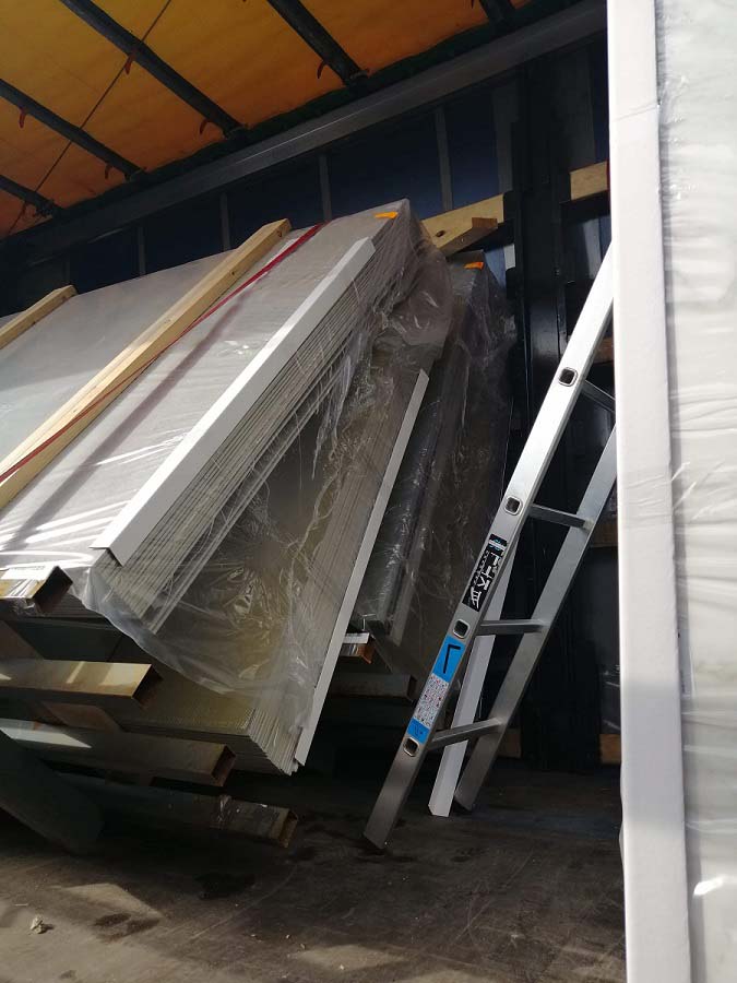
Figure 3 [Raymond Lausberg]
Figure 3 shows the two A-frames side by side as they nestle cosily in the tarpaulin. A wooden crosspiece can still be seen at the top of the A-frames. The purpose of this is not immediately apparent. We shall shed light on this conundrum a little later.
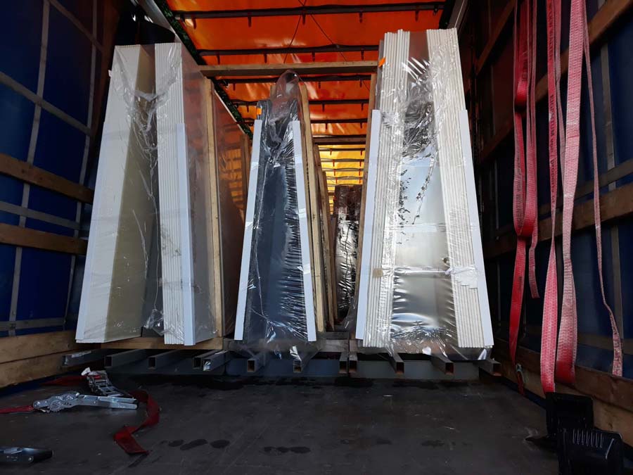
Figure 4 [Raymond Lausberg]
Figure 4 clearly shows the problem with A-frames. At the base, the A-frames are positioned as a tight fit to each other as they should be. As their name suggests, the A-frames converge upwards like an "A", i.e. they form triangles and are therefore anything but a tight-fit. This geometry means that the A-frames are perfect examples of what "liable to tip" means. Clearly, the loaders had also noticed this, since they tried to mitigate the risk of the A-frames tipping by placing two wooden battens on top and screwing them to the two outside frames. We cannot imagine why the middle A-frame was not also included in this arrangement. The batten screwed onto the top of the two higher, outer A-frames was probably intended to prevent the tie-down lashings from pushing the A-frames together, as such lashings also exert a diagonal, inward-acting force on the A-frames. It was probably simply accepted that the middle A-frame would be able to rock back and forth as it chose.
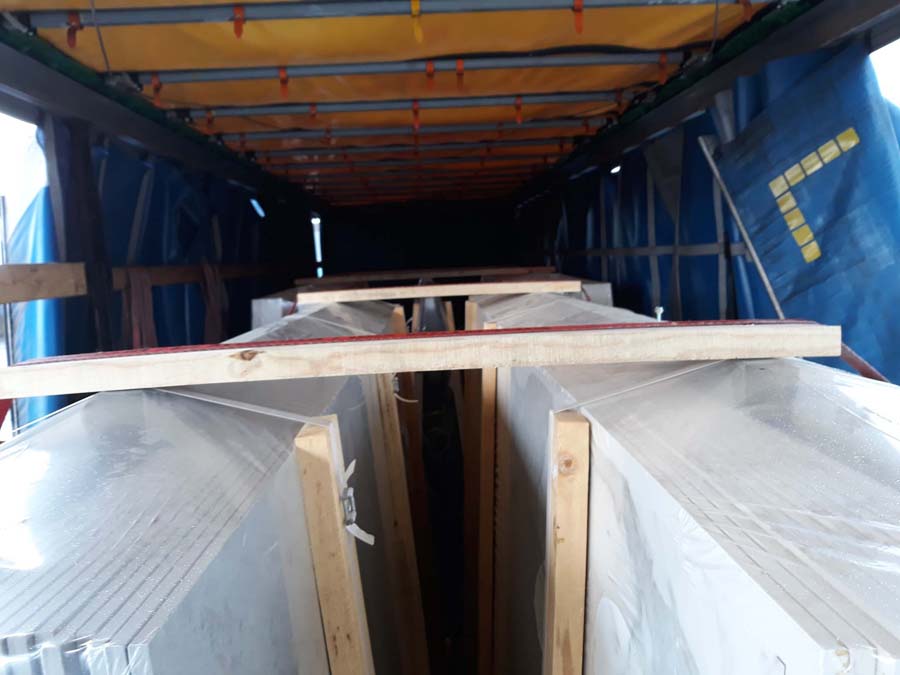
Figure 5 [Raymond Lausberg]
Figure 5 shows the wooden battens laid over the A-frames. The belts for the tie-down lashings were passed over the battens. If you look at the relatively sharp edges of the wooden battens, you might think that they would not be particularly compatible with the belts.
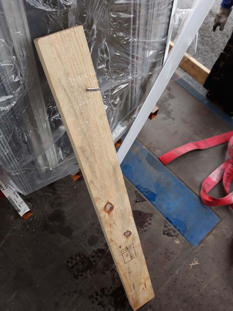
Figure 6 [Raymond Lausberg]
Let's get back to the two tilted A-frames at the front. Figure 6 shows the batten that had originally been screwed across the top of the frames. Unsurprisingly, it was unable to withstand the loads generated. In principle, it is a good idea to turn the A-frames into a "cargo block" by connecting them together securely. But this would require the use of metal bars, and these would have to be at least as strong as the A-frame itself. These steel bars would have to engage positively in the A-frames in order to connect them effectively.
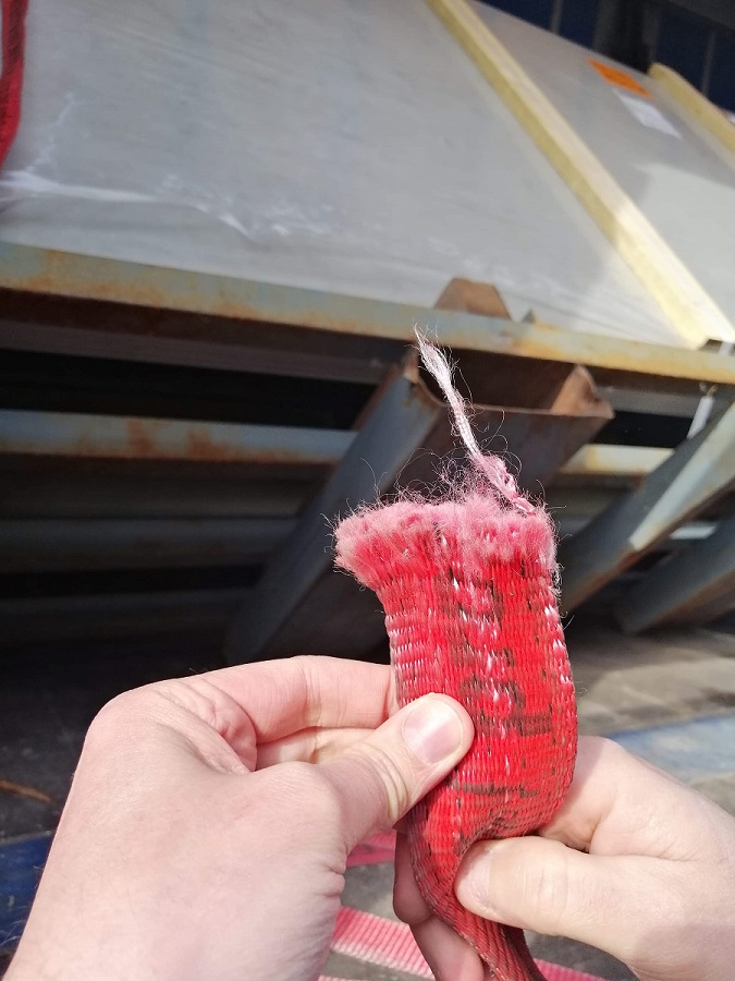
Figure 7 [Raymond Lausberg]
Figure 7 shows the dramatic effect of the sharp-edged wooden battens. The belts on the left side in the direction of travel have been cut through. At the same time, as shown in Figure 2, there were a large number of edge protectors on the floor of the vehicle. These edge protectors would at least have protected the belts from being sliced through, although it is doubtful whether they would have done a great deal of good on top of the wooden battens.
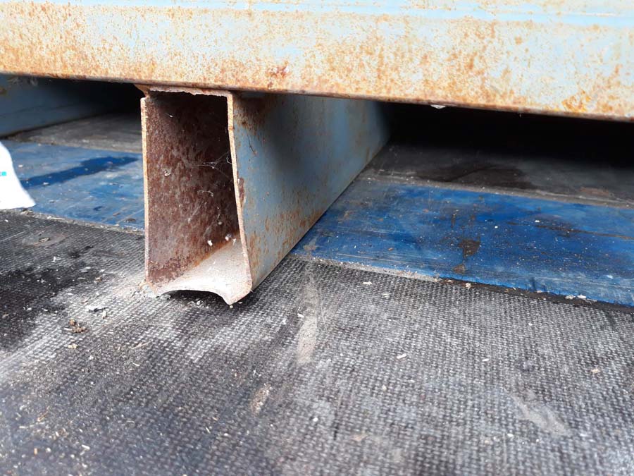
Figure 8 [Raymond Lausberg]
Figure 8 is one of our favorite pictures, as it reveals a lot of detail. On the one hand, the A-frames seem to have been used quite often, a fact that we deduce from several dents that we find on them, some of which can be seen in this picture. This photo also tells us that cleanliness of the loading bed is not something that is taken very seriously: Dirt and crumbled fragments are scattered over the loading bed, and these are more than enough to reduce the friction that can usually be expected between textured, coated board and a load of any kind. The photo also tells us that hydraulic equipment is probably often transported on this vehicle, as 3 large oil stains can be seen in this picture alone. The fact that virtually no notice was taken of friction when loading this vehicle is also evidenced by this photo. If the loaders were aware of it at all, they simply accepted the material pairings steel on steel and steel on dirty, textured, coated board with a shrug of the shoulders.
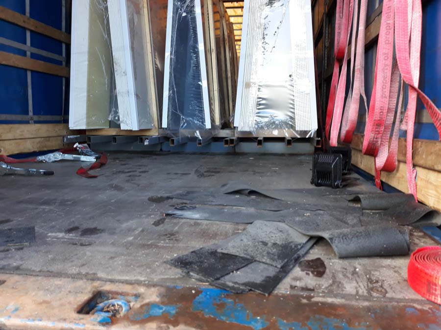
Figure 9 [Raymond Lausberg]
Figure 9 again makes us scratch our heads. There are plenty of anti-slip mats on the loading bed that have not been used, even though the intention was to secure the load with tie-down lashings. Another thing that can be seen is that the loading bed seems to have been contaminated with oil very recently, because the footprints that can be seen on the loading bed appear to be very fresh. We shall refrain from commenting on the effect of oil and dirt on friction at this point.
Assessment:
The load securing was nothing short of catastrophic. Adequate consideration was given neither to the geometry of the load nor to the load-securing method. Yes! Tie-down lashings were used over sharp edges and an attempt was made to lash down a load of no less than 2 × 3 tonnes with just 2 tie-downs at the front. It should be borne in mind here that the A-frames were standing on a pretty dirty loading surface and that the shape of the A-frames was anything but suitable for securing them sensibly with tie-down lashings. Figures 2 and 3 show very impressively what the load securing attempt actually achieved: nothing whatsoever.
Securing the load:
If vehicles regularly carry A-frames, it makes sense to secure them in prefabricated rail systems. If such rail systems are not present because A-frames are only carried occasionally, the frames should be loaded in such a way that
1. they are placed on anti-slip material and
2. they offer the possibility of direct lashing.
At this point we would like to digress briefly and discuss the load securing methods shown in this Photo of the Month: Two tie-down lashings for a 6-tonne load standing on a dirty loading surface with the friction pair steel on textured, coated board (and partly steel on steel). To allow a safety margin, we assume only a coefficient of friction μ of just 0.2, given the condition of the loading bed, namely dirt and oil. As far as the belts are concerned, we shall disregard the fact that they were laid over sharp edges and also that it was possible for the A-frames to tilt in towards each other, thus rendering any pre-tensioning force completely ineffective. We shall take into account that long-lever ratchet handles were used, and assume that these ratchet handles delivered 750 daN of pre-tensioning force on the tensioned side and double this value to take account of the other side. Since there are 2 tie-down lashings, we again double this value and thus obtain a pre-tensioning force of 3000 daN. But with the lousy coefficient of friction μof 0.2, this leaves just 600 daN of securing force. However, 3600 daN of securing force would have been needed for the front two A-frames.
Direct securing is the only way of connecting A-frames to the vehicle sensibly and effectively. This can be achieved by means of heavy-duty members that protrude longitudinally beyond the loading length of the A-frames, allowing direct lashings to be attached to them, or by inserting bars into the A-frames from above which
1. prevent the A-frames from tilting towards each other and
2. protrude laterally beyond the load in order to
3. offer the possibility of attaching direct lashings to load securing eyes.
Your load securing columnists as always wish you a safe and secure journey!
Back to beginning