
| Photo of the month – October 2019 |
[German version] |
Technology and the laws of physics
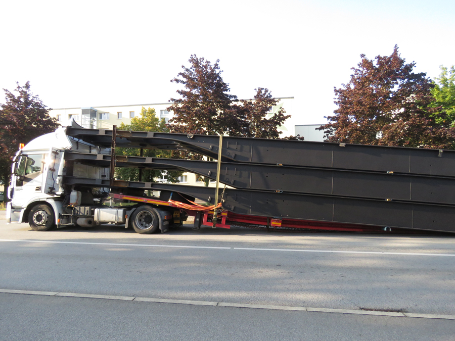
Figure 1 [Noack/Bautzen]
The story of this transport operation is relatively quickly told. An articulated truck, made up of a tractor unit and an extendable telescopic trailer was transporting steel construction elements: Chassis for railway carriages. One important piece of information is that these steel construction elements were secured with 6 or 7 tie-down lashings. One of these tie-down lashings can still be seen in all its glory. Another amazing fact is that the load is protruding far beyond the trailer and was only stopped from moving further forwards by the cab. As they moved forwards, the steel elements severed the compressed air lines of the braking system. The brakes were immediately applied to the rear axles, and as a consequence, the load should have continued slipping forwards. But it didn't. The reason??
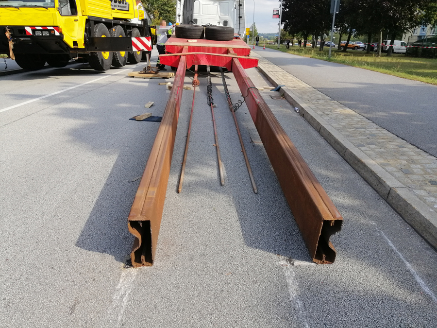
Figure 2 [Noack/Bautzen]
The vehicle reacted "intelligently" and simply left the fully braked part of the vehicle behind (Figure 5). This prevented the whole of the vehicle from braking fully and may well have saved the driver's life. The rear of the load was now dragging on the road, which slowed it down. Figure 2 shows the front section of the telescopic trailer after the cargo had been unloaded.
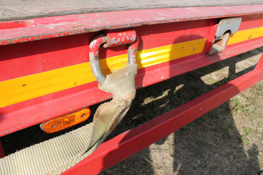
Figure 3 [Noack/Bautzen]
This photo allows us to marvel at the way in which one of the belts was attached. We do not know whether this knot was the same as the one used to tie your tie or something entirely different, but that is of no significance in respect of load securing. The important thing is that knots like this are not and cannot be suitable for securing cargo.
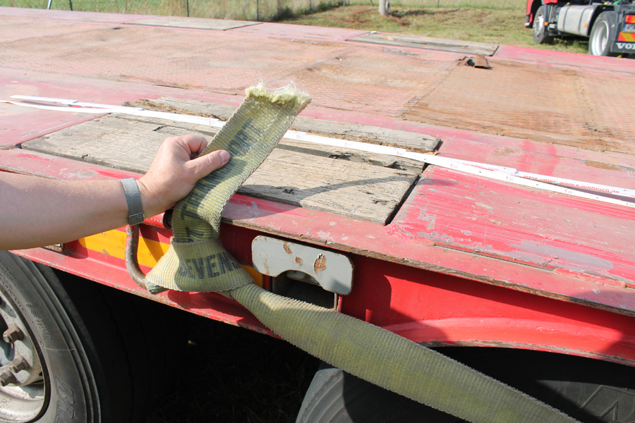
Figure 3 [Noack/Bautzen]
Unsurprisingly, some of the other belts simply gave up the ghost as the load slipped forwards. Clearly, no edge protection was used, and the belts tore or were simply sliced through.

Figure 5 [Noack/Bautzen]
Figure 5 shows the scenario that presented itself to the police officers who arrived at the scene. The rear end of the vehicle is standing abandoned on the road about 20-30 m behind the rest of the vehicle. The tractor unit continued traveling for a fair way together with the front section of the trailer and the load, which was dragging along the road. As we have said, this technical defect on the vehicle (after all, even telescopic vehicles are meant to remain connected during braking) probably saved the driver's life. Why the vehicle separated is still under investigation and has nothing to do with load securing, which is what we are looking at.
Summary:
We have given this Photo of the Month the title "Technology and the laws of physics". Technology: A part of this vehicle simply separated during emergency braking. The laws of physics: Once again, the load securing arrangements failed to withstand the deceleration forces that were unleashed here. As we have said, we do not wish to investigate the technical defect. But we do want to have a look at the way in which the load was secured.
How to secure the load:
It is actually possible to secure steel elements such as these economically using tie-down lashings. But the technique has to be used absolutely consistently. In other words, each layer must be dealt with in turn in such a way that all the individual elements must be entirely isolated from each other in terms of friction (unless they are welded together). The intermediate dunnage is flat, with a rectangular cross-section, which we regard as positive, and is something we call for in virtually every Photo of the Month. Now, it is only necessary to use sufficient tie-down lashings to provide 8000 daN of pre-tensioning force. Of course, adequate edge protection needs to be provided.
Anyone who reads our column regularly will be aware of our preference for direct lashings. The securing capability of a belt, a chain or a wire rope does not result from the muscle-power used in establishing a pre-tensioning force, but rather from its ability to offer a lashing capacity of, for example, 5000 daN when loaded in a straight line. We have used the example of 5000 daN because the belts shown here seem to be particularly wide, and we suspect that they are indeed able to offer 4000 or 5000 daN of securing force. This securing method allows you to secure a load far better with the same number of belts. But the one method does not exclude the other. Rather, they complement each other. The high level of friction provided by anti-slip mats can only take effect when minimal securing arrangements ensure that vibrations etc. cannot break the friction bond. In this case, this means that at least 2 tie-down lashings are a sensible precaution. Because the good level of friction fully takes care of securing the load to the sides and to the rear, the direct lashings to be attached only have to act against forward movement. We would attach them to each of the top two steel elements and pass them back in such a way that the belts are approximately the same length. This would be done on both sides.
If anti-slip material has been used properly and the load has been secured correctly there is a shortfall in securing force to the front of 4800 daN (if the load weighs 24 tonnes). We recommend attaching a total of four direct lashings to the top two steel elements. Under normal circumstances, each direct lashing delivers 2000 daN of securing force. This provides a total of 8000 daN of securing force. Depending on the angles involved, this is reduced a little. Because we do not know the angles, we shall subtract a generous 2000 daN, still leaving 6000 daN of securing force, which is sufficient to secure this load in the direction of travel. There are some people who would accuse us of leaving the bottom part of the load inadequately secured. Our response:
Before the direct lashings attached to the two top parts of the load can develop their full securing force, the load has to slip forwards slightly. Depending on the angles involved, a few millimeters or centimeters will usually be enough. After the load has slipped, the full securing force of the belts acts on the load. In other words, the entire weight of the top two steel elements acts on the bottom element and they are restrained by the direct lashings. One might expect that the bottom element of the load would slip out from between the loading bed and the top elements of the load. But because the entire weight of the top two elements and the friction are acting on the bottom element of the load and the top elements are being restrained by the direct lashings, the effect is that they secure the bottom element. In addition, there is the pre-tensioning force of the tie-down lashings used for minimal securing and the vertical components of the direct lashings, which are now fully loaded.
In the actual case shown in the photos, these last comments are of no relevance as the three elements of the load were all welded together with structural steel (as seen in Figures 1 and 5).
Your load securing columnists as always wish you a safe and secure journey!
Back to beginning