
| Photo of the month – September 2018 |
[German version] |
The banana bender
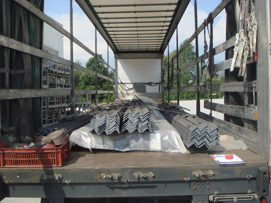
Figure 1 [Karl-Heinz PACHOINIG]
Figure 1 shows a regular curtainsider vehicle loaded with steel. The steel has a relatively homogeneous shape and is packaged in bundles of L-section and bar steel, which have been grouped into acceptable loading units. It appears that the load itself has been loaded as a tight fit, but we cannot really imagine what exactly the plastic sheeting over the bundled bar steels is supposed to achieve. We suspect that it is intended to act as a sort of dust protection, since the sheeting can hardly provide protection against the sharp edges of the L-section loaded on top of the bundles of bar steel.
The box on the left in the picture shows us that the vehicle is generously and properly equipped with load-securing materials, and the associated ratchet handles can be seen hanging on the right. The load itself is secured with tie-down lashings, which surprises us a little, given the weight, which we assume to be 22 tons.
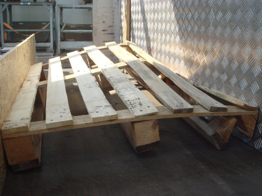
Figure 2 [Karl-Heinz PACHOINIG]
It takes a little imagination to work out why we chose the title of this month's Photo of the Month from this picture. But we found the way that this pallet had been bent like a banana in the "crumple zone" between the load and the end wall interesting, indeed, almost artistic. Even if we sometimes come across as a little sarcastic, this Photo of the Month shows that a great deal of sound thinking has gone into securing this load. We have rarely seen a tight fit that has been designed with so much thought. The dimensioning left a little to be desired. After all, how are the 3 cross-members of the pallet supposed to transmit the forces from the load to the end wall without being destroyed? In addition, there is no means of distributing the forces at the end wall. If sensible lumber had been used here, the OSB board would have given way first and, if that had been properly reinforced, the end wall would have suffered at least some dents. On the positive side, the front wall is already reinforced.
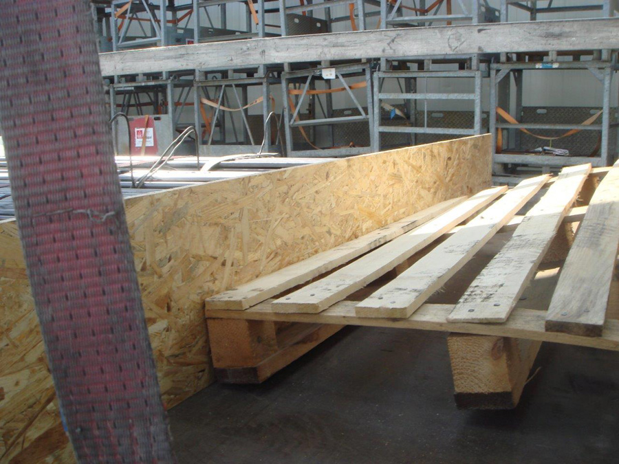
Figure 3 [Karl-Heinz PACHOINIG]
But the pallet forms a tight fit between the load and the end wall, the load itself has been loaded as a tight fit to the upright OSB board and thus forms a good bond right up to the end wall. If the palette had been placed the other way round, i.e. rotated by 90°, the result would certainly have been entirely different.
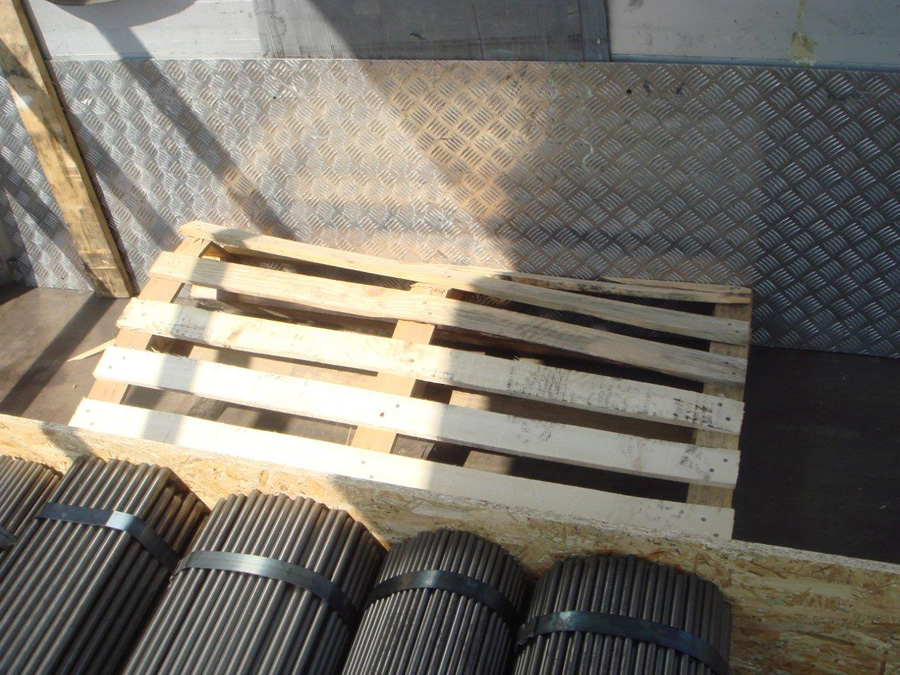
Figure 4 [Karl-Heinz PACHOINIG]
It is exactly this accuracy during loading that we are thinking of when we talk about tight-fit loading, even if the load may ultimately have slipped tight against the OSB board. A tight-fit means that the load is tight against the elements that are to transmit the force to the end wall. And that's that!
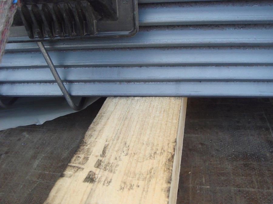
Figure 5 [Karl-Heinz PACHOINIG]
As we have already seen in Figure 1, we are dealing with tie-down lashings here, so let's take a close look at friction. In the literature we often find values for μ of 0.4 for steel on rough-sawn wood. With the contact surfaces we see here, we would tend to be careful using a value of 0.4 for μ. Remember the photo taken from the rear: The load is made up of L-section steel that only rest on two edges, like a roof. The entire load with its full weight is stacked on top of these. It is true that, as a rough approximation, friction is proportional, but if the pressure of the load becomes so high that it pushes into the material like the blades of ice skates, the wood could be changed by compaction, thus causing an attendant change in the coefficient of friction. Load securing is all about safety, so we as load securing columnists consider it entirely appropriate to assume a maximum coefficient of friction μ of 0.3 in this case. The same assumption applies to the bundles of steel bars, as they touch and compress the wood in a similar way.
With a total load weight of 22 tonnes, a securing force of 17,600 daN is needed to secure the load to the front. Since we have assumed a coefficient of friction μ of 0.3, friction takes care of 6600 daN of this total. This leaves 11,000 daN that needs to be provided by load securing measures. Unfortunately, we do not know how many tie-down lashings were attached to the load. Since there are 3 load blocks and we have seen that 2 tie-down lashings were used on the rear load block, we assume that 2 tie-down lashings were also used at the front for each load block. We therefore assume a total of 6 tie-down lashings with a lashing capacity of 2500 daN each and a pre-tensioning force of 400 daN per belt. Although we have friction losses over the load, the physical principle that for any action, there is an equal and opposite reaction, means that the pre-tensioning force does not disappear, but also acts to secure the load by friction. Therefore we shall simply double the 400 daN (at a lashing angle of approx. 50°), giving 6 × 800 daN of pre-tensioning force, a total of 4800 daN. The securing force from these tie-down lashings is calculated by multiplying by the coefficient of friction μ of 0.3. This gives us a total of 1440 daN of securing force, leaving 9560 daN for the tight-fit to the front. Again, we shall give the benefit of the doubt to the person responsible for securing the load and assume that the correct vehicle has been chosen and that it is a Code XL vehicle. Unfortunately, the only weak point was the pallet that took on the form of a banana. If the forces had been correctly passed and distributed to the end wall, the load would have been nicely secured to the front.
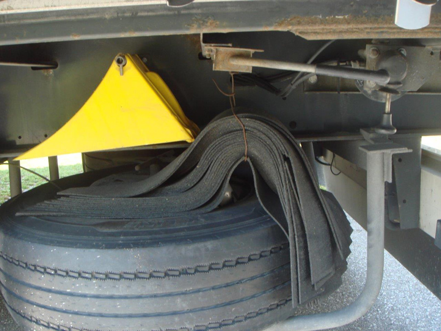
Figure 6 [Karl-Heinz PACHOINIG]
Figure 6 shows how the driver has artfully attached a considerable quantity of anti-slip mats to the vehicle above the spare wheel. Why this anti-slip material has not been used is not clear to us. Perhaps the driver was afraid that the very narrow contact surfaces and the high pressure would destroy his anti-slip mats. Perhaps he thought that his elaborate tight-fit securing arrangement against the end wall would not bend like a banana, but rather achieve the desired effect. Having said that, we have not as yet discussed securing to the sides and to the rear at all.
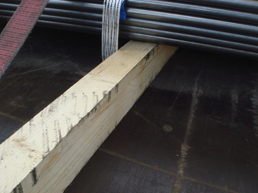
Figure 7 [Karl-Heinz PACHOINIG]
What we see in Figure 7 is, once again, square cross-section dunnage. Normally this fact would make us flush with anger, but since the assumption in this case was that the load was effectively secured as a tight fit against the end wall, and consequently could not theoretically slip forwards, we shall refrain from yet another lecture on square dunnage today. The available anti-slip material would easily have allowed the dunnage to be covered top and bottom. This would have significantly improved friction. At this point, however, we would like to revisit our discussion of the contact surface. As we have seen, these were not fully vulcanized, heavy duty mats. These mats have several advantages in respect of oil and water, but they are not as robust as fully vulcanized heavy duty mats. If the L-sections press against these rubber mats with their long edges only, rather like an ice skate as described above, the mats will in all probability be squashed simply by placing the load on them, and they will be destroyed or ground to dust the first time that a force acts on them. Such lightweight mats are entirely suitable for use under the dunnage in order to increase friction, but we would recommend fully-vulcanized, heavy duty mats on top of the dunnage.
Let's do the load-securing calculation with the anti-slip mats:
Friction μ = 0.6
Total load to the front: 0.8 minus 0.6 μ = 0.2.
(80 % acceleration – 60 % friction = 20 % remaining securing force to the front)
22,000 daN weight force x 0.2 give a remaining securing force of 4400 daN.
Total pre-tensioning force: 6 tie-down lashings at 800 daN pre-tensioning force = 4800 daN
Securing force: Total pre-tensioning force x friction = 4800 daN x 0.6 μ = 2880 daN
Shortfall in securing force:
4400 daN (required residual securing force to the front)
– 2880 daN (securing force)
= 1520 daN (shortfall)
4400 daN overall securing force required to the front minus 2880 daN result in a shortfall in securing force of 1520 daN.
We can in all probability assume that the pallet would have had no chance against this shortfall in securing force either. But if we had placed it so that it was rotated by 90°, the load distribution on the loading bed would still have been good, and it would probably also have coped with the shortfall in securing force.
It will come as no surprise to regular readers of this column that we would have preferred to use direct lashings, in the form of loop lashings, for securing the load to the side. Although we would have needed 12 belts instead of six, we would have improved the securing effect to the side many times over. Since the loop lashings are also pre-tensioned, it would also have been possible to assume a corresponding pre-tensioning force for improving friction in this case as well.
Your load securing columnists wish you a safe and secure journey into September!
Back to beginning