
| Photo of the month – February 2017 |
[German version] |
Steel thingummy
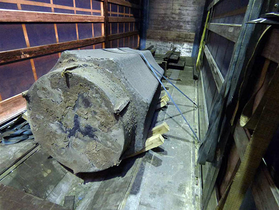
Figure 1 [Peter Scholz]
This load comprises a solid steel tool, probably used as some kind of rotating element in the steel industry. Apart from that, we cannot say a great deal. On account of its shape, we shall call this steel thingummy a "toothed roller", which is undoubtedly not the correct term, but it seems appropriate. The toothed roller weighs in at 15.8 tonnes and is clearly abominably secured with just two tie-down lashings. It is resting in a coil well that was "lined" with eight pieces of squared lumber (four on each side).
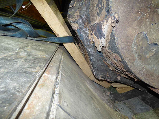
Figure 2 [Peter Scholz]
Coil wells are exceptionally well suited for securing cylindrical loads to the sides. The clever thing about coil wells is their slanted side walls. They are ideal for transporting common coil formats and split strips. They are loaded in such a way that the coils are supported only by the side walls of the coil well. They must be completely unsupported in the middle. As a result of being supported at the sides, cylindrical loads will generally be well secured to the sides. The load is generally secured to the front by loading it as a tight fit against stanchions, which are (or must be) additionally secured using heavy chains or belts.
As experienced load-securing columnists, we always believe that people are well-intentioned and we will therefore assume that in this case, the lumber that is "protecting" the sides of the coil well against the toothed roller was put there deliberately. If we take another look at the entire load in Figure 1, we have to doubt whether it really made any great sense to insert these four pieces of lumber on each side. The lumber causes all the pressure from the load to be concentrated on just four points on the side walls of the coil well. Whether or not this makes sense is a question that should be addressed to the maker of the vehicle. Figure 2 shows very clearly how the "tooth" of the toothed roller has worked into the wood, how the ends of the squared lumber are standing up on both sides and how there is now just a very small point of contact with the sides of the coil well.
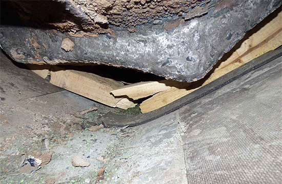
Figure 3 [Peter Scholz]
If we look at Figure 3, we have to ask whether in fact four pieces of squared lumber were inserted on each side or whether it was not the case that four pieces of lumber were placed on top of the coil well and the toothed roller was slowly lowered onto them, causing them to break under the load of the toothed roller and thus "fit themselves" to the coil well. Clearly, the entire thing was not thought through, since Figure 3 shows that anti-slip material was used under the squared lumber, but not on top. In Figure 2, we can see some scraps of anti-slip material in the bottom of the coil well, but none can be seen on the walls and between the toothed roller and the lumber.
Figure 4 shows the toothed roller from the front:
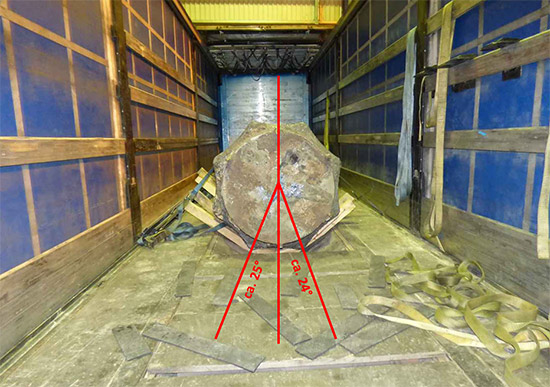
Figure 4 [Peter Scholz]
There is no tight fit to any stanchions or to the end wall of the coil well, nor can we see any securing measures that would have prevented this toothed roller from slipping forwards. We will deal with securing the load to the front later. At the moment, we are focusing on the way in which the load is secured to the sides.
As a rule, coil wells are constructed in such a way that coils are supported in them and that the point of contact to the side of the coil well is at an angle of more than 30° to the perpendicular through the center of the coil. The geometrical background is that the sine of 30° is 0.5 and we need to provide load securing to the side for 0.5, or 50 % of the weight of the load. This is therefore a perfect solution for securing the load to the sides.
In the case of our toothed roller, two neighboring teeth are being supported by the coil well. Our attempt to reproduce this in a sketch resulted in angles between 24° and 25°. Clearly, those responsible for loading had given precious little thought to the angle at which this huge steel load was supported. An attempt could have been made to position the toothed roller in such a way that the tooth after the next one had been in contact with the coil well. If not, extensive load securing measures would have been needed to secure the load to the side. Because we cannot reconstruct the actual geometry accurately, we do not know whether it would actually have been possible to position the roller in such a way as to ensure that the lines of contact with the coil well coincided with the tooth after next of the toothed roller. The prerequisite for securing a cylindrical object in this way is that it is only in contact with the side walls of the coil well. The object must not rest on the base of the coil well. If you did not want to lose this option for securing the load, the alternative would be to position the toothed roller a little higher in the coil well by inserting suitable dunnage to prevent the middle tooth from making contact with the bottom of the coil well. A sufficient number of pieces of dunnage would need to be used to prevent excessive pressure being exerted on the side walls and ensure that the lumber can withstand the pressure.
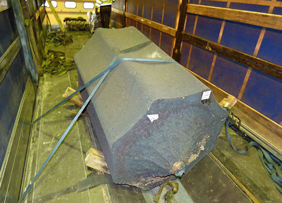
Figure 5 [Peter Scholz]
The load securing measures that were taken are indeed rather pitiful. They comprise two tie-down lashings passed rather artistically over the toothed roller to cross each other and then clearly tensioned to the hilt. We have no idea why the lashings were passed over the load diagonally: The load-securing points are clearly located in such a way as to allow them to have been passed straight over the load.
The load was secured to the front solely on the basis of friction. In order to better assess the level of friction we are dealing with, let us cast our eyes back to Figure 2, where we can see that the surface is extremely corroded and that considerable amounts of rust have already flaked off. The entire surface is extremely rough and is supported by the squashed lumber. Because friction is always determined by the weakest link in the chain, we need take no further notice of the level of friction between the roller and the lumber. Figure 2 shows that there is no anti-slip material between the lumber and the coil well. This means that the friction is determined by the material pairing of squashed, rough-sawn lumber and textured coated board.
Because the extremely high pressure has probably changed the surface of the lumber, we shall err on the side of caution and take a coefficient of friction μ of 0.3. Because the toothed roller weighed 15.8 tonnes, there was a shortfall of 7900 daN in terms of the securing force to the front. Even if we are very generous (and generosity is no friend in matters of safety) and assume a coefficient of friction μ of 0.5, we still have a shortfall of 4740 daN to the front.
Let us have another look at how this load was secured in practice: The only load-securing measures taken to secure our toothed roller to the front were friction and two tie-down lashings. At a pre-tensioning force of twice 600 daN and a coefficient of friction μ of 0.3 (ignoring the angles), these delivered 360 daN of securing force. Even if these values were doubled, they play no significant role in securing the load.
Note for load-securing experts:
Anyone who has read up a little on load securing and physics will know that the "bilge and cantline" way in which the load is stowed in the coil well also acts to secure the load. This is the result of the forces that are additionally generated by the load "jamming" between the sides of the coil well.
Let us take an example: If you attempt to stack a pencil on top of two pencils lying tight next to each other by putting it in the "saddle" between them, the two bottom pencils will roll away to the sides. These forces achieve their highest values just before the third pencil drops through the gap. Among other things, these forces mean that logs that are stacked and transported between stanchions experience an additional securing effect. But because this effect is not described in any of the guidelines and regulations and depends to a large extent on the angles and surfaces involved, we have ignored it for the purposes of this utterly amateurish attempt at securing a load, and hope that our readers will forgive us.
So how can a toothed roller like this be secured well?
We have already discussed securing to the sides in the context of the coil well. If there is still any shortfall in terms of load securing force, loop lashings are of course the method of choice to keep this monster in place. And to secure the load to the front, direct lashings using chains or belts are a suitable method, although the equipment must, of course, be protected against the sharp, abrasive edges of the toothed roller. Let us remind ourselves that (depending on the angles involved) one direct lashing is able to deliver 4000 daN of securing force. As we have already said, it is important to use edge protectors and to ensure that all direct lashings acting in one direction should be of the same length.
If it is possible to secure a toothed roller or any other cylindrical load to the sides using a coil well, we believe that it is vital to use tie-down lashings to prevent it from rolling out due to dynamic forces. In this case, it is important to keep the lengths of the belts as short as possible to keep residual stretch to a minimum. Alternatively, chains can be used, which have far less residual stretch. In this way, the tie-down lashings act as direct lashings against the load rolling out of the well dynamically.
Your load securing columnists as always wish you a safe journey!
Back to beginning