
| Photo of the month – September 2016 |
[German version] |
And yet it moves!
It is the year 1633, the year in which a certain Galileo Galilei was forced to abjure his belief that the earth moved around the sun. Legend has it that, having narrowly escaped execution by the inquisition, he was heard to mutter the words "… and yet it moves," under his breath as he left the court.
Of course, we are but simple load securing columnists, and do not wish to be so arrogant as to compare ourselves with the mighty Galileo Galilei. But it sometimes appears to us that we are arguing a hopeless case against an inquisition of movement-deniers when we talk of load securing.
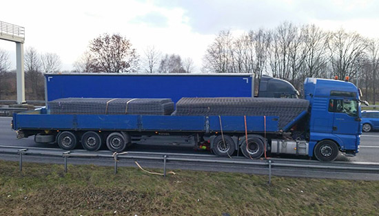
Figure 1 [Siegfried Serrahn]
Admittedly, the outward appearance of the load, comprising what is commonly called steel reinforcing mesh, seems to offer plenty of interlocking and plenty of friction, insofar as we want to talk of friction here.
Unfortunately, the opposite is true. Measurements have demonstrated that steel reinforcing mesh such as this has a coefficient of friction μ of just 0.2. As is so often the case, Figure 1 shows only tie-down lashings or torn and failed tie-down lashings, and too few of these, given the weight of the load.
We do not wish to make the mistake of using this column to calculate that 96 or 162 belts would be needed to secure the load in this way. We simply wish to ask the question, in the name of physics and Galileo Galilei, why the load was not secured as a tight fit. We cannot, of course, be certain how Galileo, who was among other things an accomplished physicist, might have secured this load. But he probably would not have attempted to press down on the load in order to marginally increase its miserable level of friction.
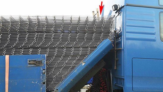
Figure 2 [Siegfried Serrahn]
Figure 2 shows nicely where the tie-down lashings had been placed, as the load has been deformed at this point (see arrow). In other words, the load yielded, and the absence of the belts themselves means that they were sliced through by the protruding rods when the load slipped.
And the end wall also appears to have decided that discretion is the better part of valor and yielded in the face of overwhelming force. The driver can count himself lucky that the packages he was carrying were not higher, otherwise the damage to his cab would undoubtedly have been far greater.
So how can loads like this be secured effectively?
We touched on the answer above: by loading the mesh as a tight fit or by using direct lashings. In the case of direct lashings, there is the problem that the lashings have to be passed over the load, which is not a simple one to handle, and that the pre-tensioning force will cause some slight damage to at least part of the load. The simpler solution is undoubtedly to use stanchion systems that can be inserted in different positions, depending on the size and shape of the packages of steel reinforcing mesh.
Solutions:
As is so often the case, there are many different approaches to solving the problem:
- On the one hand, we should here mention the VDI Guideline, Sheet 11 on securing concrete reinforcement steel. This prefers the use of direct lashings for securing purposes. This is a good solution for vehicles that do not often transport loads such as this. On the Internet, you will be able to find videos of trials for this method, as you can for many other approaches.
- For anyone who transports loads such as this on a regular basis, a tight-fit load securing system that is integral to the vehicle offers a number of benefits. We look at two examples below:
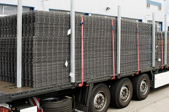
Figure 3 [Siegfried Serrahn]
Figure 3 shows a stanchion system that features different socket positions for the stanchions, at least at the front, thus providing a certain amount of flexibility. As always, it is the tight-fit that is important, which means that the load must be loaded tight up against the front stanchions. Of course, the manufacturer of the stanchions must provide information on the load capacity of the stanchions, e.g. in the form of a stanchion chart.
Additional direct lashings acting at the top of the front stanchions can be used to significantly increase the securing force provided by these stanchions. If narrower mesh is being carried, it is also possible to insert the side stanchions in different sockets. Stanchion systems are also available that have a screw mechanism that allows the stanchions to be moved in flush with the load.
From our point of view, a tight fit achieved by the stanchion systems integral to the vehicle is an extremely good solution, as the person responsible for securing the load does not have to clamber up or over the load. Whether or not systems such as these make economic sense will vary for different scenarios.
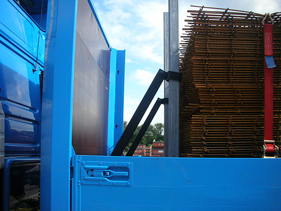
Figure 4 [Siegfried Serrahn]
Diagonal supports can also be used to provide additional support to the front stanchions. Again, it is important that the manufacturer informs the users of the securing forces that are provided by these systems.
Your load securing columnists as always wish you a safe journey!
Back to beginning