
| Photo of the month – July 2016 |
[German version] |
The physics of steel
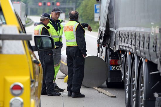
Figure 1 [Roland Halkasch]
This photo speaks volumes: so much so that we load-securing columnists could just sit back and let the implications of the photo sink in. But we are who we are, and in our passion to improve the world of load securing, we are happy to analyze this case, as it offers us plenty of ideal starting points.
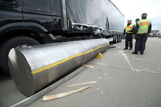
Figure 2 [Roland Halkasch]
What is lying on the motorway here weighs no less than 16 tonnes. It goes without saying that the motorway is no place for a load such as this. The steel roller fell from the loading bed to the left, hit the road, slid a short distance and then came to a standstill, thankfully without injuring any third parties. The roller is most certainly solid metal: This is not a tube with a cap on the end. No, we are looking at 16 tonnes of solid steel that has broken loose. Reports also reveal that, either as a result of the manufacturing process or for reasons of corrosion protection, this steel roller was coated with grease or anti-corrosion oil. As far as we are concerned, the important thing is that grease or oil has a decisive impact on friction.
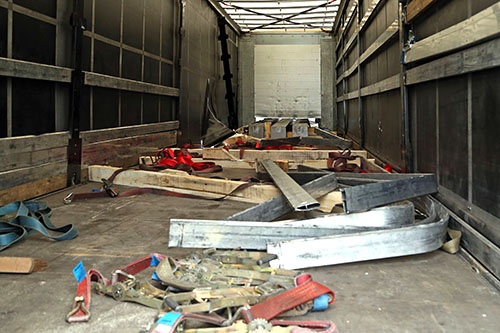
Figure 3 [Roland Halkasch]
In the foreground, we can see several long-lever ratchet handles. Behind these, there are some removable aluminum slats, all of which have been deformed in the same way, and behind these there are 4 pieces of wooden dunnage, which actually have a slightly rectangular format (which is something we have always insisted on) and wedges that were intended to secure the load as a tight fit to the sides. In the background of the photo, we can see three square bars, which are also clearly made of solid steel. Judging by the light coming in, they appear to have penetrated the end wall.
At the back of the photo, we can also see where the tarpaulin was penetrated on the left and the gap where the removable slats should have been and which can now be seen, deformed by the roller, in the foreground. There is nothing on the loading bed itself to indicate why the steel roller should have fallen from the vehicle to the left rather than simply slipping forward. This could have been caused by the way in which the dunnage may have tipped, a possible sloping road surface or by the driver steering to the right a little. And we can also clearly see that the front left stanchion was torn from its anchorage by the steel roller during the dynamic process and is now pointing forwards at an angle.
Load securing:
We are told that the steel cylinder was "secured" with 4 or even 6 tie-down lashings. The securing equipment failed at several points. We are told that this included broken fixtures, but this could have happened as the steel roller fell off the loading bed. We shall discuss this later.
To start with, a few basic comments about the type of securing used,
namely tie-down lashings. Tie-down lashings act on the basis of the simple physical principle of applying downward pressure to increase the apparent weight of the load, thus achieving a greater securing effect as a result of the increased friction.
As we have already mentioned, the load was for some reason coated with grease or oil. The relevant guidelines state that if the loading surface or the load is contaminated, a coefficient of friction μ of 0.2 must be used for calculations. We tend to regard this as a helpful guideline value, which is not intended to override logical thought processes. Not every loading surface that is slightly contaminated demands that a coefficient of friction μ of 0.2 should be used. Many loading surfaces, particularly those with only slight contamination, would allow a coefficient of friction μ of 0.3 to be used.
But in this case, we have an extremely heavy load with a minimal contact area with sawn lumber. Not only that, the smooth load is also lubricated. The high weight of the load compresses the wood at the point of contact, which means that the wood becomes smooth and is also lubricated. We would be surprised if a coefficient of friction μ of 0.1 actually applied after all these factors were taken into consideration. Anyone who even attempts to secure a load with tie-down lashings given such a level of friction has undoubtedly never taken part in any load-securing courses.
Several questions spring to mind: Why has the driver never attended a load securing course and why does he have to risk his own life and that of others with a load like this? But first and foremost, what loader neglects his responsibilities so recklessly and sends a vehicle like this, that is so badly loaded and ludicrously secured, onto the roads? We are, quite frankly, utterly dumbfounded, and it is our earnest hope that the loader has been confronted with this information.
Ultimately, we cannot from our perspective judge whether three or four pieces of dunnage were used. If it was three, the 16 tonnes were distributed over three linear contact areas, each of which was bearing a load of 5.33 tonnes (5330 daN). Which begs the question whether the loading bed was designed for such loads. And if it was four, then there was still a concentrated load of 4 tonnes (4000 daN) acting over precisely the width of the wooden dunnage. This may have been just within limits, although a weight of this magnitude is not distributed evenly across such "thin" dunnage. But we should have a look at the issue of load distribution in a separate Photo of the Month.
Dunnage:
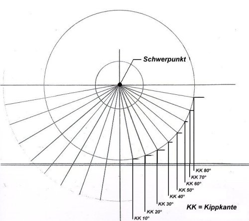
If we take a look at the dunnage, we find the edges of logs, wedges nailed to the lumber and chamfered beams that are intended to provide a measure of "tight fit" to the load. But what does a load like this need if a genuine tight fit is to be established to the sides? What are the angles that need to be observed, and what theoretical and practical measures would be needed to actually restrain the load to the sides? The easiest answer would simply be to say that a vehicle with a coil well should be used. In this case, the coil, or rather the steel roller, having a diameter of between 0.8 m and 1.0 m, would "hang" in the well, ensuring that it was only in contact with the sides and was not touching the floor of the well at all. Let us explain this with the following diagram:
| Angle (a) | sin a |
| 10° | 0.17 |
| 20° | 0.34 |
| 30° | 0.50 |
| 40° | 0.64 |
| 50° | 0.77 |
| 60° | 0.87 |
| 70° | 0.94 |
| 80° | 0.98 |
| 90° | 1.00 |
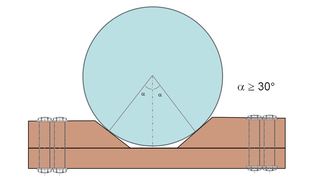
Diagram 1 [GDV]
The diagram represents a steel roller and shows a whole range of tipping edges at 10-degree intervals. The contact surface of the roller with the oblique surfaces can actually be regarded as the tipping edge. To calculate the force needed to secure the load to the sides, we need to use the factor 0.5. In this case (securing to the sides), friction can be discounted, as the roller is round and the rolling friction is negligible. We would therefore need a contact surface located at 30 degrees or more from the perpendicular.
If these wedges are intended to take on the role of securing the load to the sides, they must be positioned in such a way that
- the steel roller can be positioned so that it is resting solely on the wedges and
- is in contact with them to the left and right at an angle of 30 degrees or more, i.e. 35 or 40 degrees, and that
- the center of the roller is not resting on the loading surface or the dunnage.
Only if these conditions had been fulfilled would the wedges have been able to secure the load to the sides. One fundamental prerequisite, however, is that the wedges are firmly connected to the underlying dunnage so that they are able to withstand the pressure from the load. A couple of little nails put in with a nail gun, as was done here, most certainly do not do the job. What is needed here is rectangular dunnage and wedges that are properly bolted to the dunnage and so on.
The sensible cradle that we have described above sadly has little to do with what we find in this Photo of the Month. The wedges used here were purely a safety at work measure to ensure that the staff were not risking their lives during loading.
So how might the load have been secured to the sides properly?
That's quite simple. Anyone who reads our column regularly will already have muttered to themselves "with loop lashings". And so it is: The necessary securing force to the sides is 0.5 x 16 tonnes, i.e. 8 tonnes or 8000 daN. Theoretically, this means that 2 x 2 loop lashings to each side would be enough.
This 2 x 2 tonnes or 2 x 2000 daN means that the securing arrangements would be dimensioned exactly at the limits of the load securing equipment. But because the height of the roller results in an angle of 30° – 40°, which reduces the strength of the loop lashing slightly, this would put us very slightly below the 2000 daN. And so, in order to be on the safe side, we would urgently recommend 3 loop lashings from each side. This would secure the load properly to the sides.
Securing the load to the front presents rather more of a problem. As we have said, the oil and grease which coats the load probably reduces the coefficient of friction μ on wood to 0.1. Anti-slip mats are generally tested when contaminated with oil and should also deliver a coefficient of friction μ of 0.6 under these conditions, i.e. when they are oily and contaminated with grease. Because the load securing experts who read our column regularly will have used proper rectangular dunnage and covered it liberally with heavy duty mats, possibly completely vulcanized, it is possible that the oil will form an unbroken film on the anti-slip mat. For safety reasons, we shall simply reduce the value of μ from 0.6 to 0.3. This means that a total securing force of half of 16,000 daN is needed to secure the load in the direction of travel and 20 % of 16,000 daN still have to be achieved with securing measures.
Again, we shall turn to direct lashings. If we need to restrain 8000 daN to the front, and if we use long belts to ensure that the resulting angles are negligible, 2 belts would again be theoretically adequate, but we shall again use 3 belts in order to be on the safe side. To the rear, we shall content ourselves with a single belt as a loop lashing (2 x 2000 daN) as we only need 3200 daN in this direction.
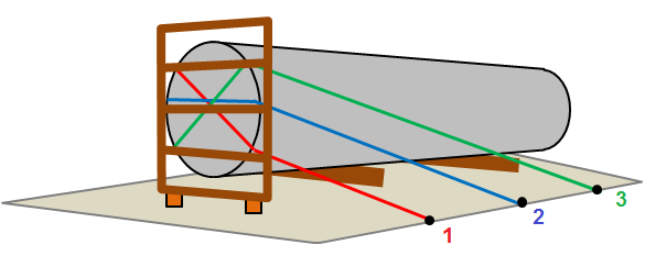
Diagram 2 [GDV]
Securing the load to the front demands a little imagination, as the geometry of the steel roller makes it a little difficult to secure. Because the direct lashings are only able to develop their securing force when the load moves slightly, we have to ensure that two conditions are met:
- the belts must be the same length,
- they must be able to move freely and slide against the load.
This means that they must not block each other. In order to achieve this, we shall use a pallet placed on end in front of the steel roller (see Diagram 2). Its sole purpose is to keep each of the belts in place. We shall take the front belt (red) from the left side through the bottom of the pallet and then up to the right of the vehicle, where it is attached to the third load securing point. We shall take the second belt (blue) through the middle of the pallet as close as possible above the center of gravity to the other side, where it is also attached to the second load securing point. And we shall take the belt from the third load securing point (green) through the top of the pallet, down to the left-hand side of the vehicle and out through the pallet back to the first load securing point.
This ensures that the belts are almost exactly the same length and will be subject to equal loads if the cargo moves. It goes without saying that good, systematic edge protection is absolutely crucial here. It is, of course, also possible to use chains in combination with suitable edge protection. In order to ensure that the belt securing the load to the rear does not slip off, but acts as close as possible to the center of gravity, we recommend that a pallet is also placed on end in front of this end of the steel roller. The three loop lashings that secure the load to each side should be spread as evenly as possible along the length of the steel roller to stabilize it.
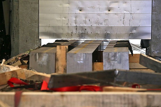
Figure 4 [Roland Halkasch]
The three square bars at the front of the loading area that we mentioned above were "secured" with 3 tie-down lashings. The lashing belts appear to be intact, and the pre-tensioning force appears to have been maintained. The belts have also not been damaged, as the edge protectors did their job. But the abominable level of friction and the fact that tie-down lashings are an entirely unsuitable securing method for this scenario mean that the three square bars not only perforated the end wall, but actually smashed through it and only came to rest against the driver's cab. When choosing this securing method, great care was taken to ensure that the square bars did not come into contact with each other. They obviously have sensitive surface finishes. But if great care was to be taken about anything, we would far prefer it to have been taken in ensuring that the loaders secured these square bars sensibly rather than in the almost entirely ineffectual way that we see here.
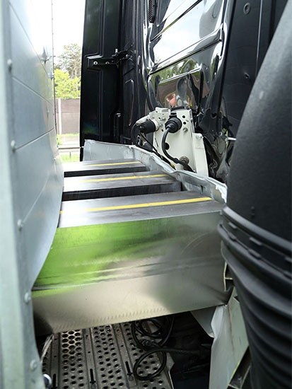
Figure 5 [Roland Halkasch]
The square bars not only smashed through the end wall; they also caused considerable damage to the driver's cab. We don't need to point out that the driver sits behind this first steel panel and probably felt pretty uncomfortable when the load came knocking at the cab after he had braked.
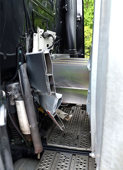
Figure 6 [Roland Halkasch]
The damage is likely to be very extensive, and we can again only hope that this will be a lesson not only for the poor driver, but also for the loader in particular. These photos should
- be displayed in a prominent position at the loading ramp and
- provide sufficient reason to give comprehensive training to everybody from all three shifts involved with the loading process. People could easily have been killed or injured here.
One would hope that the carrier is perceptive and understanding enough not to throw the book at the driver, who will already have had a deeply traumatic experience. Rather, he should without delay send him on an effective training course. And in this context, we have to ask ourselves why the carrier chose to send a driver who clearly only had a mastery of tie-down lashings, and beyond that had little idea about effective lashing, to pick up a load that demanded such considerable load-securing skills.
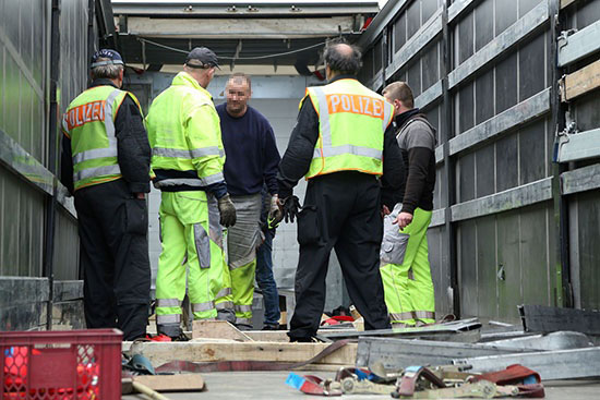
Figure 7 [Roland Halkasch]
Discussing at length the whys and wherefores of how this accident could happen.
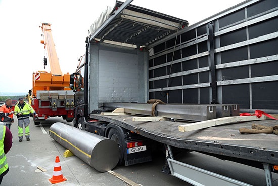
Figure 8 [Roland Halkasch]
And this photo also speaks volumes. The loading bed was significantly deformed when the 16-tonne steel roller fell from it. We conjecture that the steel roller not only tore through the load securing equipment, but also broke off the fittings when it fell to the road. The loading bed was not only deformed as a result, but its surface was also scratched. The scratches on the loading surface and the marks on the concrete road surface almost form a straight line.
Which means that the vehicle must have been virtually at a standstill when the steel roller slipped from its original position. Here, we can clearly see that the square bars shifted forwards by about 3/4 – 1 m before their kinetic energy was completely converted into deformation energy.
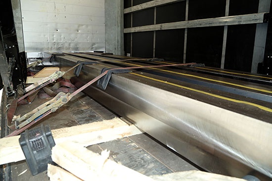
Figure 9 [Roland Halkasch]
When the load was secured, long-lever ratchet handles were used, which is praiseworthy, although they offered no special advantage given the securing method that was chosen. We originally thought that the black strip on the almost square dunnage was an anti-slip mat, but on closer inspection it turned out to be nothing more than "skid marks". So what we have is no anti-slip mats, a senseless attempt to secure the load with tie-down lashings, good edge protection and a very sad end to the story.
Load securing:
So how can a load like this be secured? Once again, the answer is simple: With well thought-out direct lashings. The load comprises three square bars, each weighing approx. 3 tonnes, making a total weight of around 9 tonnes. These have to be secured to the front, to the sides and to the rear. We would, of course, use anti-slip mats again and because of the oil, we would once again reduce the value of μ to 0.3 to be on the safe side. It is not that we don't trust the anti-slip mats, but we just want to be absolutely sure that our load stays exactly where we put it.
It goes without saying that one can rely on the manufacturer's specifications and take the specified value for μ of 0.6, even when the mats are contaminated with oil, provided that the manufacturer guarantees this value. We wish to make this clear at this point. But if you look at the total additional outlay we propose, it amounts to no more than one or two belts. For us, the additional safety margin is worth it.
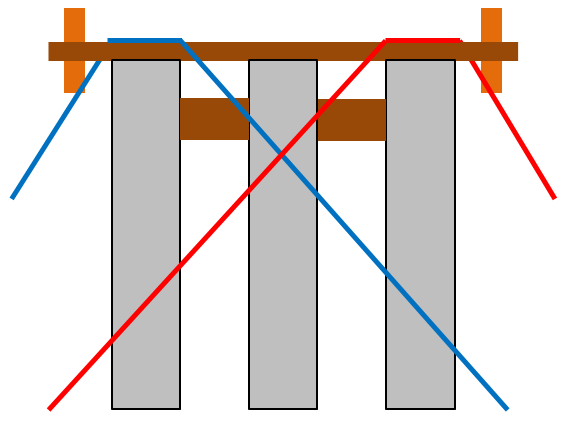
Diagram 3 [GDV]
Our proposed securing arrangement again uses 2 loop lashings from each side, and only one additional edge protector is needed. To prevent the square bars from slipping forwards, we need 2 loop lashings or head loops. Again, we have to show some imagination, as the middle square bar could slip out if we simply applied loop lashings with no further measures. And so we will stack at least 2 pieces of squared lumber on 2 or 3 pieces of dunnage laid lengthwise. The squared lumber can then be secured to the rear with loop lashings. Special care must be taken to ensure that there is no contact with any sharp edges, either over the load or against the load. The belts must be protected from such sharp edges with edge protectors or protective sleeves.
Diagram 4 shows the securing method we recommend from a different perspective:
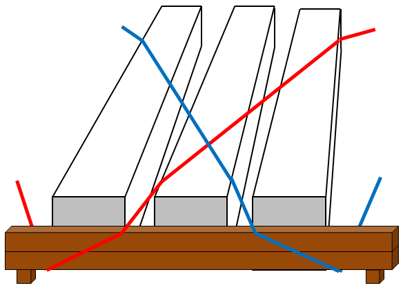
Diagram 4 [GDV]
Your load securing columnists as always wish you a safe and secure journey!
Back to beginning