
| Photo of the month – June 2016 |
[German version] |
Load distribution
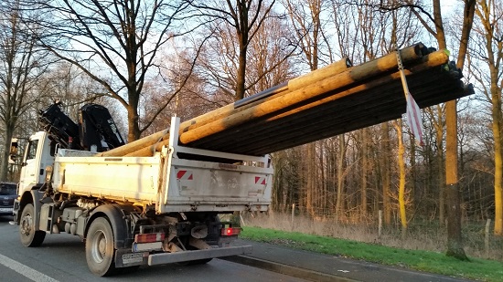
Figure 1 [Wolfgang Jaspers]
If you see a vehicle like this on the motorway, you can't help but look. Why? To start with, because it looks different from the rest of the trucks on the road.
Even if the perspective in Figure 1 tends to exaggerate things, there is a sense that something is very wrong here.
The load appears to be overhanging massively, and, at first sight, it does not appear to be adequately secured.
The photographer was fortunate in that the driver stopped at a lay-by. So it was possible to take a few more photos and have a word with the driver.
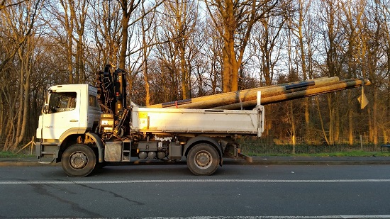
Figure 2 [Wolfgang Jaspers]
Seen directly from the side, things do not seem quite so bad. The tire on the rear axle is somewhat compressed, and the wheel arch at the front seems to be rather high. That surely can't be because of the load, after all, the truck is hardly carrying anything.
Or maybe it is …
Let's have a look at the load. It comprises a total of 31 telegraph poles. Each of them weighs around 200 kg. This gives a total load weight of 6200 kg.
Surely this 18-tonne truck is allowed to carry that?
Correct! The truck has a maximum payload of 7140 kg. Which means that it is not at its limit. Theoretically, it could take another 940 kg. Only the weight of the driver needs to be subtracted.
Before we go into detail, let's have a quick look at how the load is secured.
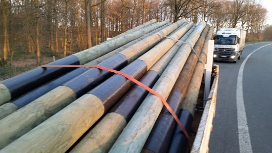
Figure 3 [Wolfgang Jaspers]
A cross-beam has been fixed towards the back of the loading bed (this can be clearly seen in Figure 7), and the poles are resting on this. This is a good solution. The tailgate is not subjected to the load, and the construction gives the load a tight fit to the sides, as can be seen in Figure 3.
The wooden poles are resting against the end wall at the front, and they form a tight fit to the sides against the side walls.
To prevent the poles from slipping or bouncing vertically, they are lashed down with a total of three tie-down lashings.
The lashing points on the loading bed are quite capable of taking up the forces generated by lashing down the load. They each have a capacity of 2000 daN.
The load securing deserves good marks. The owner of the vehicle or the person responsible put some thought into this.
Although the overhanging load still seemed odd to him. But even here, he was leaving nothing to chance.
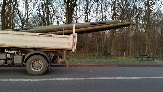
Figure 4 [Wolfgang Jaspers]
To go back to the telegraph poles: They are each eight meters in length. Over almost half their length, they are overhanging beyond the end of the vehicle. Is that allowed?
Extract from Section 22 (4) of the German Road Traffic Regulations (StVO):
(4) The load may project beyond the rear of the vehicle up to a length of 1.5 meters; in transport operations over distances of up to 100 km, however, up to a length of 3 meters; journeys made outside the territory covered by the present Regulations are not taken into account. Vehicles or combinations of vehicles must not be longer than 20.75 meters, including the load.
If the extreme end of the load projects more than 1 meter beyond the rear reflectors of the vehicle, it is to be made conspicuous by at least
1. one bright red flag not less than 30 x 30 cm in size and kept straight by a cross-bar;
2. one light red sign of the same size hanging at right angles to the direction of travel; or
3. one vertically attached cylindrical body of the same color and length with a diameter of at least 35 cm.
These safety devices must be affixed to the load not higher than 1.5 meters above the carriageway. If necessary (section 17(1)), at least one red lamp is to be affixed at the same place and, in addition, a red reflector not higher than 90 cm above the ground.
This text from the German Road Traffic Regulations states that the load must not protrude more than three meters to the rear.
It also states that the load must be made conspicuous if the end of the load protrudes more than one meter beyond the end of the vehicle.
Furthermore, it states that the safety devices must not be attached higher than 1.5 m above the ground.
In this case, the load protrudes more than three meters to the rear. In fact, it protrudes by four meters. The load must be made conspicuous. This was done, as can be seen clearly in Figure 6. But the height is far greater than the maximum permitted 1.50 m above the ground.
Special authorization is required. The person responsible at the company probably realized this and went to consult the road traffic authorities.
If an exemption to the normal load dimensions is to be made, the procedure is regulated by Section 46 of the German Road Traffic Regulations.
Excerpt from Section 46 of the German Road Traffic Regulations
Section 46 Exemptions and permission
(1) In particular cases or generally, the road traffic authorities may grant, to certain applicants, exemptions from:
?
5. the provisions governing the height, length and width of vehicles and loads (second sentence of section 18(1), section 22(2) to (4));
?
The relevant administrative regulations state that exemptions can only be granted if the load is indivisible.
The applicant must specify the dimensions of the vehicle and describe the load in the application.
The staff at the road traffic authority of course checked whether the load being transported was indivisible. Dividing a telegraph pole is problematic, as it can no longer be used for its intended purpose if it is too short, and so this criterion is met. But the staff at the road traffic authority failed to consider that the load projected to the rear beyond the drive axle by about 3/4 of its length, and thus formed a very long lever that would massively reduce the load on the steering axle. At the same time, the drive axle is subjected to excessive load.
Despite this, an exemption was granted for this indivisible load with an overhang of four meters. The only condition imposed (other than permitted times) was that due care should be taken when turning off in order to ensure that the protruding load did not pose a risk to following traffic or oncoming traffic. So far so good.
Unfortunately, the person who issued the special authorization only received a written application. If he had seen a photograph of the consignment, he may have realized that load distribution is a problem here.
In this case, the load is so poorly distributed that the vehicle is no longer balanced. The vehicle can no longer be driven safely.
The person responsible at the transport company now has a clear conscience, and the driver is in possession of a document that will help him to emerge unscathed from any possible police inspection.
Sadly, that is just one side of the coin.
The authorization does not concern itself with the forces generated by the load that act directly on the vehicle during normal driving maneuvers, such as braking and steering to avoid obstacles. It is the implacable laws of physics that apply here. The photo below reveals signs that the drive axle is overloaded.
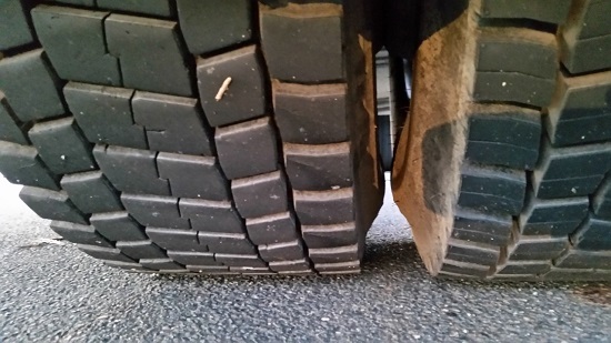
Figure 5 [Wolfgang Jaspers]
The driver must be able to recognize this. As Figure 5 shows, the tires have bulged so much that their walls are very close together. This is an indication that the axle may be overloaded. And the fact that the tires are compressed (Figure 4) suggests the same thing.
Another indication of overloading that not many people know about is something known as the "Russian overload indicator".
If more than three tread blocks are flat on the road surface, the axle may be overloaded. See Figure 5a.
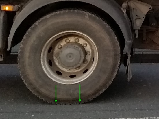
Figure 5a [Wolfgang Jaspers]
Five tread blocks are in contact with the road surface. Which is another sign that the axle is overloaded.
Now let us have a look at the next photo:
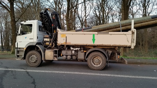
Figure 6 [Wolfgang Jaspers]
The load application point is marked. This is the point on the loading bed at which the center of gravity of the load must be located in order to comply with the load distribution plan described in VDI Guideline 2700, Sheet 4.
If there are no stipulations to the contrary in the operating instructions, this point is in the center of the loading bed both longitudinally and laterally. If necessary, the point must be determined mathematically as laid down in the Guideline.
In this case, the center of gravity of the load is located approximately at the end of the loading bed, and hence around two meters too far to the rear. Because it is behind the drive axle, the load acts as a lever, having a negative effect on the steering axle. This axle should, however, bear at least 20 % of the actual weight of the vehicle. This stipulation is also from VDI 2700, Sheet 4, the "load distribution plan" as well as a regulation from the BG Verkehr (the German transport trade association).
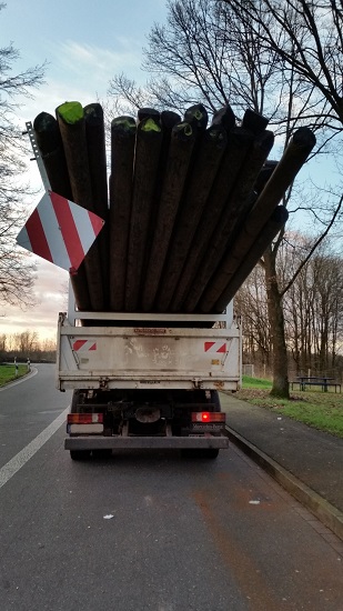
Figure 7 [Wolfgang Jaspers]
This is undoubtedly not the case here. The lifting effect on the steering axle causes too little force to act on the road. This in turn means that the vehicle can no longer be driven safely.
So what is the solution here?
This load cannot be transported on this vehicle in compliance with the relevant regulations.
It is quite simply not a suitable vehicle. Loading and transporting this cargo is therefore not permitted.
Because the driver transports the same load every day, the vehicle used must be one with a sufficiently long loading bed. Such vehicles are available on the market.
This case should also serve to sharpen awareness of this issue at the authorities that grant such exemptions. They should, wherever possible, request a photo or at least a sketch of the planned transport arrangement. Perhaps this would make it possible to deal with problems such as these before they arise.
Your load securing columnists as always wish you a safe journey!
Back to beginning