
| Photo of the month – April 2016 |
[English version] |
Soldier stowage?
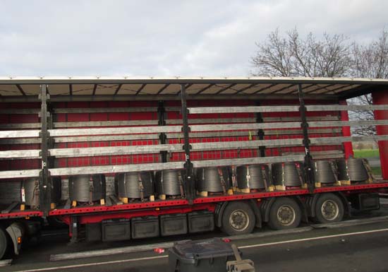
Figure 1 [Wolfgang Jaspers]
Despite the martial sound of the heading we have chosen for this Photo of the Month, it is merely intended to reflect the pattern in which these coils were loaded, namely in tidy rows. The load is a full load with a total weight of 24.57 tonnes. The coils have been loaded onto the vehicle in pairs and, as can be clearly seen from the side, with a considerable gap to the end wall, as dictated by the load distribution plan. The common center of gravity is to be found after 4 ½ pairs of coils. This is approx. 80 cm in front of the first of the rear axle assemblies, which is enough to satisfy the most critical observer. Clearly, some thought was given to load distribution when loading this cargo, and these considerations obviously led to the correct conclusions. So we shall award top marks here.
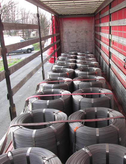
Figure 2 [Wolfgang Jaspers]
When we get a little nearer to the vehicle and have a closer look at how it is loaded, we see that the cargo is loaded in straight lines, which is, at least initially, pleasant to see. Load securing equipment has clearly been used. So it is quite possible that this may turn out to be an example of good loading practice.
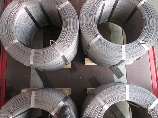
Figure 3 [Wolfgang Jaspers]
But this photograph destroys any illusions that we may have had about the quality of the load securing. The load is made up of coils, each weighing 1,365 kg. Although they are standing next to each other in pairs, and the coils in the pairs are touching each other, there are large gaps in the load along its length. Which means that we cannot call this "soldier stowage", as this would refer to a stowage method where the coils are touching each other both laterally and longitudinally. The load securing equipment was only attached on the orders of the officers who inspected the load. We can only assume that those responsible had originally relied solely on the good level of friction provided by the anti-slip mats cheekily protruding here and there under the load.
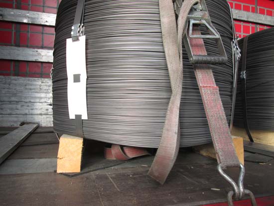
Figure 4 [Wolfgang Jaspers]
This photo shows us how the wire coils are standing on somewhat knock-kneed upright rectangular dunnage. Although this dunnage is "secured" to the coil with a steel strap, the stability of this connection does not exactly fill us with confidence. The anti-slip mats have been placed diagonally under the load, but it is largely a matter of chance whether they increase the friction or not. But because load securing can never be left to chance and must always be a matter of certainty, any attempt to increase friction in this way is to be regarded as no attempt at all and must be deemed "unsatisfactory".
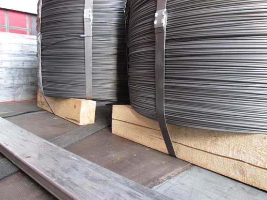
Figure 5 [Wolfgang Jaspers]
Figure 5 impressively documents how the dunnage, which is intended to act as a skid, is largely standing on the friction-enhancing mats purely by chance and is often in full contact with the loading surface. When anti-slip mats are used in this way, it must be assumed that the applicable coefficient of friction is the far lower one arising from the pairing of textured coated board and rough-sawn lumber, and sometimes, as can be seen in the foreground of Figure 5, painted steel plate. Correct use of anti-slip material would have avoided all this.
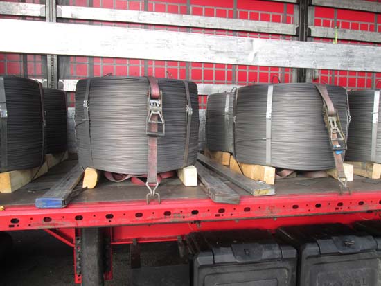
Figure 6 [Wolfgang Jaspers]
In Figure 6, we can see not only a piece of dunnage with a rounded corner from the side of the log, which emphasize the knock-kneed instability of the load, but also 3 "cargo planks". These cargo planks were probably inserted between the removable aluminum slats as a load-securing measure. Cargo planks are simply clamped into position, which means that they operate purely on the principle of friction. It is difficult to say what securing effect they actually have. We shall assume that it will be somewhere between 50 and 150 decanewtons. The information provided by the manufacturers indicates that they are eminently suitable for preventing stacked, light cargo from toppling over. But they are not designed to stop wire coils with a weight of several tonnes from slipping forwards. This is not what they are intended for, and it is not a role that they are capable of fulfilling.
But Figure 6 also reveals something else, namely the reason why the coils were loaded with gaps between them. Undoubtedly, those responsible gave this some thought: The coils were placed exactly centered behind the corresponding load securing points. This ensured that the belts (which were sadly never used) could be passed across the center of the load. And after the inspection, it could be seen how accurately the load had been positioned.
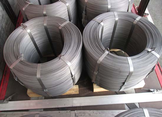
Figure 7 [Wolfgang Jaspers]
This photo clearly shows the triangular rings (4 per coil), each of which was secured to the coil with a steel strap. Attached to the coil is a drawing and a warning text indicating that these rings are intended to be used for lifting, but are not to be used in conjunction with a noose. Instead, they have to be used with chains fitted with a spreader (see diagram 1). If there is a relatively shallow angle between the lifting chains, the forces acting on the rings will be extremely high. This is intended to protect those who are handling this load from such forces.
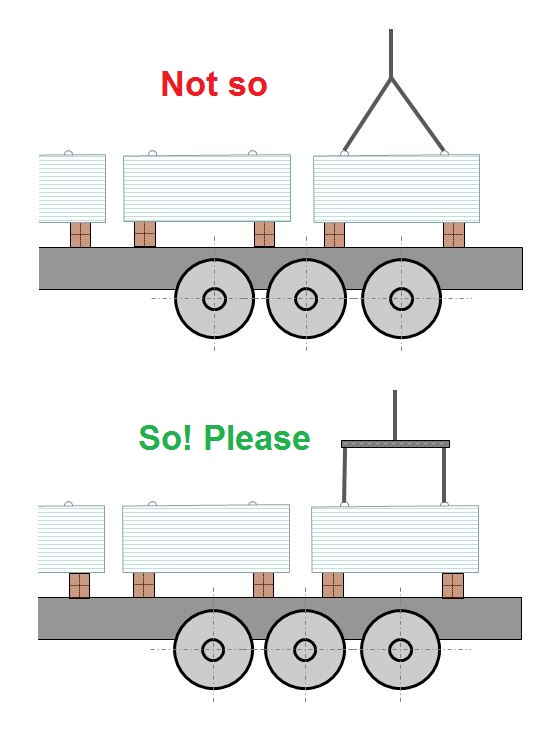
Diagram 1 [GDV]
In the event that the lifting gear is attached in such a way that there is an opening angle, considerable additional forces can act on the rings, depending on the magnitude of the angle. Because the capacity of the rings is given as just 800 daN, such additional forces should be avoided at all costs. The use of a spreader counteracts the inward forces directed towards the eye of the coil.
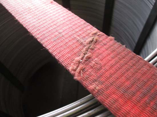
Figure 8 [Wolfgang Jaspers]
Even though this vehicle is used to transport steel, it is carrying good (not worn) load securing equipment. All the ratchet handles are long-lever type handles and, although the belt material shows signs of use, it is all fit to be used, with the exception of the belt shown in this photo.
Summary:
The packaging of the load gives a very good impression. The steel straps appear to be very robust and the fact that a method has been provided for craning the coils safely and moving them with a forklift truck indicates that some thought has gone into this packaging. We are unaware of why the dunnage has been placed on end. We can only guess that the intention was to leave the largest possible gap between the load and the loading bed to minimize the risks associated with the use of a forklift truck. We believe that proper skids with at least 2 lateral members would improve the packaging (load unitization), but we have to admit that we have no experience with integrated dunnage such as this.
The loading method:
We have already criticized the amateurish way in which the anti-slip materials have been positioned and give this the lowest possible marks. The way in which the coils were positioned was intelligent and precise, namely directly in front of the load securing points. This deserves a good B+ grade. Clearly, those who were responsible had no faith in the recesses in the outer longitudinal member. These could also have been used as load securing points. Perhaps it would have been harder to close the tarpaulin if these load securing points had been used. Perhaps the tarpaulin would have worn more quickly, because the hooks would have penetrated it. Or perhaps it was far easier and more efficient to use the additional load securing points fitted to the loading bed. But then one has to ask why the belts were not actually used.
Load securing:
After the inspection, each pair of coils, weighing 2.739 kg, was secured with a belt fitted with a long-lever ratchet handle. If we assume a pre-tensioning force of 750 daN on the tensioned side and a K value of 1.8, and also take a coefficient of friction μ of 0.6 (if the anti-slip material is placed under the load correctly), we get a securing force of 810 daN. Because the required securing force would only have been 546 daN given a good level of friction, the load could have been secured in this manner.
However, the relevant guidelines and regulations now state that every item of cargo (including pairs of coils) must be secured with 2 tie-down lashings if that item is standing freely and not as a tight fit against other parts of the load. This only applies, of course, if it has been decided that tie-down lashings will be used to secure the load. The background to this regulation is simply that it should not be possible for parts of the load to twist free of the belts that are securing them. Because the load in this example is cylindrical and is being transported upright (the winding axis is vertical), it is not possible to attach a second belt to these pairs of coils to prevent them from twisting free. It is possible to comply with this regulation by loading these coils as a compact unit (i.e. as a tight fit to each other) and securing them as a block. If this is done, the coils cannot twist out from under their securing belts, as they are supporting each other. This meets the requirements of the regulation, provided that a loop lasing is used to prevent single elements at each end of the block from twisting out. However, if the cargo is loaded as a block, the load securing points on the outer longitudinal members of the loading bed have to be used.
Closing comments:
There is much in this example that shows good intent, but the fact that the coils were loaded in front of a load securing point, but were in fact never lashed down (this was only done after the inspection) is completely beyond us. The strapping around the coils was good, and the dunnage was creative, although it did not inspire a great deal of confidence. Overall, the lack of friction and the absence of tie-down lashings meant that the load securing was worse than inadequate, and this is entirely the fault of the loader and, of course, the driver. The vehicle itself is well equipped with load securing equipment, anti-slip mats, cargo planks and lashing belts, all of which would deserve a grade B. We would like to think that loaders, in particular, would think these things through thoroughly, and that if the effort is made to place the load so precisely in front of the load securing points, a check should be made to ensure that the driver has actually lashed the load down, otherwise all the careful positioning in the world will be a waste of time..
Your load securing columnists as always wish you a safe journey!
Back to beginning