
| Photo of the month – December 2015 |
[German version] |
Load securing material vs granite
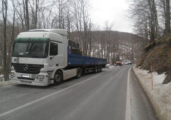
Figure 1 [GDV]
Once again, we feature a loading method that is well on the way to becoming a regular in our column. Stone slabs or, more accurately, polished granite slabs, have been loaded onto A frames along the length of the vehicle for transportation. So far so good. Flat, slab-like loads should be transported upright. This applies equally to tiles as it does to granite slabs, and indeed to plate glass and any flat products that are susceptible to breakage. But observant readers will probably have noticed that either this vehicle has been loaded in blithe disregard of load-distribution considerations, as the only visible load is just behind the front end of the trailer, or that some of the load has parted company with the vehicle unexpectedly. And the second of these possibilities is the case.
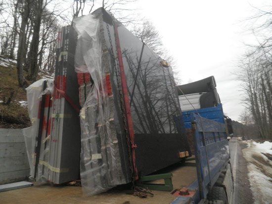
Figure 2 [GDV]
Although granite is a byword for strength and resilience, when it is cut into slabs and then so highly polished that you can see the forest reflected in it, it becomes delicate and susceptible to breakage. If we take a look at this masterpiece of a load unit, we noticed that the A frame clearly has a very narrow base. We do not know whether the granite slabs were standing on lumber in order to protect them, but if they were, the lumber was purely decorative. From the shrapnel that was once the other A frame, we know that the pairs of A frame legs were not held together in any way. The green A frames are standing directly on the loading surface without any attempt whatsoever having been made to distribute the load or, crucially, increase the friction. The load unit in itself is rather a work of art, but it was nevertheless bizarrely secured. Extremely delicate slabs were bundled together with long-link chains to form a "load unit". Pieces of wood were pushed under the edges to protect the corners. Although it has to be said that "under the edges" is not an accurate description: The wood was simply pushed somewhere in the vicinity of the edges and the genius that created this load unit clearly hoped that the long-link chain would somehow manage to keep the wood in place once it had been tensioned. But because there was clearly not enough wood available, they resorted to a rubber mat or anti-slip mat towards the back. This appears to be somewhere between 2 and 5 mm thick, and we think that it is not unreasonable to doubt the efficacy of this attempt. On the other hand, the additional belt used to bundle the unit is a wonder to behold. It is not merely past its best; far from it, it has long been fit only for scrapping.
But despite this, it was quickly tied together and used to bundle the granite slabs. Then again, an impressive amount of care has been taken here: This belt clearly sports an edge protection sleeve – at least at the top, although we can't see one at the bottom.
Load securing
The absolute highlight of this load is the way in which it is secured. Situations such as this are always ideal for our purposes, as a vehicle such as this almost certainly provides us with a before and after snapshot. Even if the second A frame was not "secured" identically, the end result of this transport operation suggests that the load securing measures were at least similar. Whoever was responsible for this load, weighing in at somewhere between 8 and 12 tonnes, simply lashed it down with a single belt. It is not enough that a tie-down lashing was chosen to secure such a heavy load where there was so little friction, after all, tie-down lashings simply artificially increase the weight of the load to increase the friction; no, to make things worse, the belt has also been passed over the side wall. By their very nature, belts are somewhat flexible and elastic, but practitioners know how to use the pre-tensioning force to cope with this. The drawback here is that the belt has additionally been passed over a relatively flexible surface. The movement of the side wall impacts on the pre-tensioning force. Perhaps the perpetrator of this attempt to secure the load thought that in this case the loss of a few decanewtons was neither here nor there, as this is not a real way to secure a load and is a huge gamble anyway.
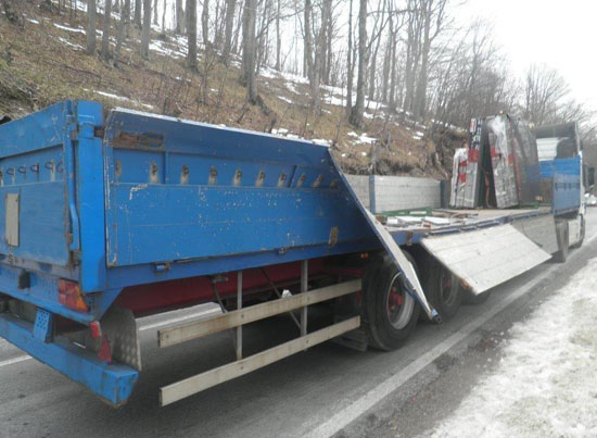
Figure 3 [GDV]
As we have already said, the second load unit on this vehicle parted company with the trailer in a relatively gentle left-hand bend. It appears that the load broke through the side wall by sheer brute force and tipped onto the roadside and the embankment.
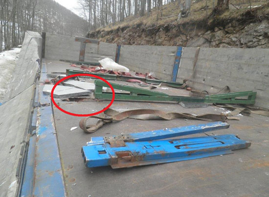
Figure 4 [GDV]
The evidence on the vehicle provides further insights into how the accident unfolded.
Because we received very few hard facts, we unfortunately have to content ourselves with conjecture. At the front of the photo you can see the two green base elements of the A frame. There was clearly nothing connecting the two A members together. This meant that the stone slabs also had the task of stabilizing the A members in relation to each other to form a frame. Our understanding of loading frames is that they are intended to help transport a cargo efficiently and, above all, safely. But the idea that loading frames should be held together by the loads they carry before they can work properly does not exactly tally with what we understand to be safe loading practice. At least not in this case. The use of separate A frames like this to create a safe load unit may perhaps work when nothing is moving, but can be problematic even under gentle braking. After all, all the force generated during braking has to be transmitted to the loading surface by the A frames. The base of the A frames is very narrow, and this carries the risk that the slabs will tip the frame over as they try to move forward. At this moment, all the material used to bundle the load would loosen as the A-shaped supports would also tip over. This means that there would be nothing to stop the load from moving.
But the marks on this truck suggest that the accident unfolded rather differently. At the front of the picture, indicated by a circle, we can see a pretty large hole in the loading bed. We were not told whether or not there is also a counterpart by the second base element of the A frame, and the photos we have do not shed any light on the matter. Holes like this are generally only caused when the A frames tilt and the entire load is concentrated on one edge of the frame. If there is only a hole in the bed at the front, this could indicate that the driver may have noticed that he was taking the bend too fast and therefore braked. When the A frames tilted, the entire A frame construction, however the individual elements may have been put together (push-fit, welded or screwed), collapsed, tipping the slabs onto the bed of the truck or onto the side wall and then onto the bed. The reason why we suspect that this is what happened is that the loading bed has a significant dent that seems to be about as wide as the granite slabs. This is particularly clear on Figure 3. On the left rear of the vehicle, there is still a belt hanging over the side wall. Of course, it is only conjecture that the rear load unit was only secured with one, or perhaps two, tie-down lashings, but it is an understandable assumption to make if we look at the way the front load unit is secured.
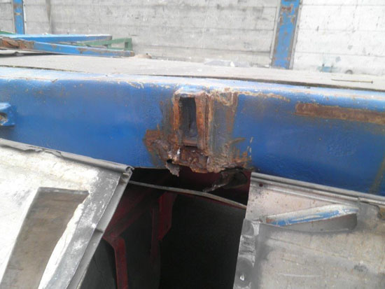
Figure 5 [GDV]
The point at which the stanchion failed shows only a small region of gray metal (if at all), and plenty of rust. The rust indicates that the stanchion mounting failed long ago, and the welds, some of which can be seen and some only guessed at, suggest attempts at repair. DIY repairs on vehicle parts always represent a pretty serious problem, because the parts should do their job just as well as new parts after they have been repaired, which clearly didn't happen here.
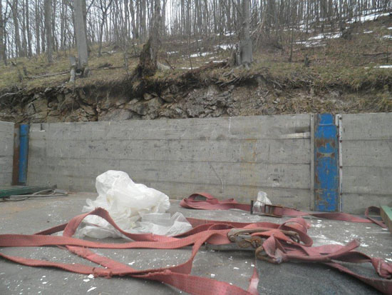
Figure 6 [GDV]
The ratchet handles and hooks that can be seen in Figure 6 show a considerable amount of rust, and the belts are fit for scrapping for several reasons. Some of the damage to the belts is clearly the result of the accident, but some is older and indicates the generally poor condition of the load-securing equipment.
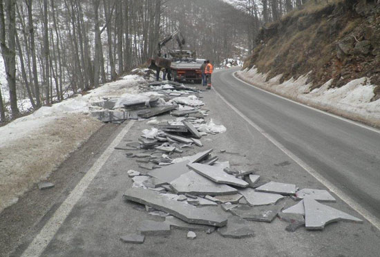
Figure 7 [GDV]
A look at the scene of the accident confirms our suspicion that the load did not slip from the vehicle all at once. Instead, it probably tipped and then gradually fell from the vehicle, which would explain such a long trail of debris. Oncoming traffic was not at risk with this accident, as the load fell towards the embankment. But if we were to imagine that the truck was traveling in the opposite direction, it would have been negotiating a right-hand bend. The right-hand bend would have exerted acceleration forces to the left on the load, and the debris we see on the road here would have been tipped into the opposite lane. If there was any significant amount of traffic on the road, the debris would have caused problems for many more than just one vehicle.?
How to secure loads like this properly
Wider A frames that are joined together securely would be desirable. Wider A frames have the advantage that they distribute the load on the vehicle well. In this example, it is to be feared that the line load capacity of the vehicle had been exceeded as a result of the narrow contact areas. Wider A frames distribute the load and give it a greater contact area, which is good for both the load and the truck. It is recommended that softwood dunnage be used between the load and the A frame. This not only offers good friction and protects the load well; the weight of the load means that the load positively engages with the frame as a tight fit. The A frames themselves should be placed on heavy-duty mats on the loading surface. This allows us to make use of our old ally, friction. One of our favorite axioms about friction is as follows: If the vehicle is braking on rubber tires, we should at least give the load a chance by giving it rubber boots, so that it benefits from something like the same friction as that between the vehicle and the road.
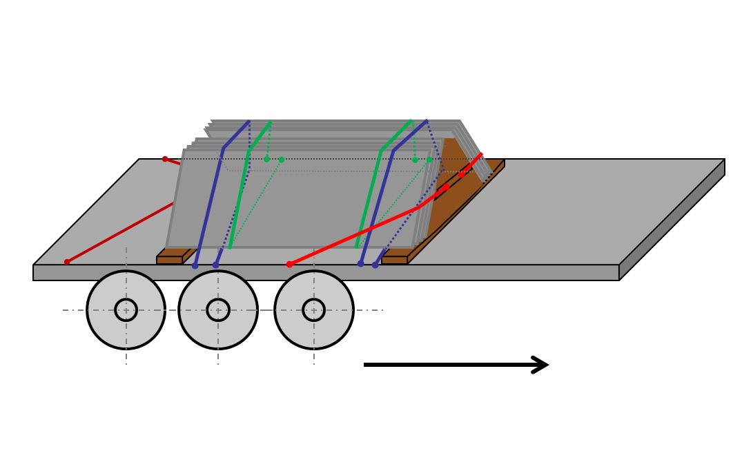
Diagram 1 [GDV]
The A frame is standing on heavy-duty mats (not shown). The loop lashings not only prevent the slabs from tipping; they also provide a minimal level of securing force to ensure that the friction is kept at a high level. The loop lashings taken from front to back hold the granite slabs on the A frame. Because the red belts are direct lashings, care must be taken to ensure that the ends are of the same length, because the load must slip forwards slightly and tension the belts in order to generate a securing effect. If the belts are of different lengths, the first pair will take the strain before the second pair.
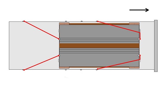
Diagram 2 [GDV]
Critics and those concerned with the economics of load securing could object to this securing method on the grounds that securing of the A frame has been "overdone". That is correct! If we assume 12,000 daN of weight force and 60 % friction, we only need 2400 daN of securing force to the front. The front two belts are actually sufficient on their own. But because these belts have a dual function (preventing the slabs from slipping forwards and restraining the A frame), we have added a second pair of belts at the back, after all, load securing is all about safety.
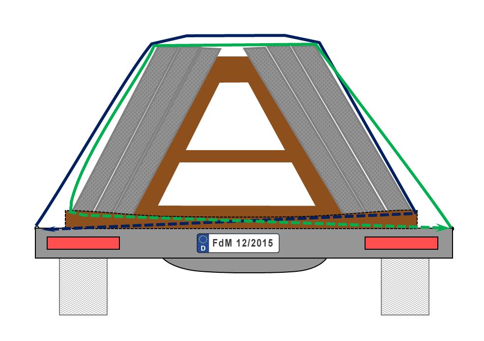
Diagram 3 [GDV]
We really don't think we need to point out that it is difficult to secure an 8 or 12-tonne load using tie-down lashings alone. The direct securing method must be used, either to secure the load and the A frame at the same time or to secure the load to the A frame and then to secure the A frame. Bundling the slabs to the A frame itself is extremely important, but an additional direct lashing should be used to prevent the slabs from slipping forwards. Our diagram illustrates an alternative securing arrangement. We secure the A frame to the front, rear, and to the sides, although the front belts could easily be placed more to the sides, as friction is sufficient to ensure that the load is secured to the rear. A minimal level of securing is ensured by the direct lashing, thus guaranteeing that the friction is always able to act fully. At the rear, the securing equipment should be taken to the load securing points at a more acute angle, since at least 20 % of the necessary securing force to the front still needs to be provided. We also recommend a further four loop lashings for loads such as this. They should be taken from each side, around the entire load and back to the same side. This will mitigate any risk of either the A frame or the slabs tipping. Advice such as this will not be found in any official guidelines, but if we consider the risks associated with a load such as this, it would at least give us considerable peace of mind if we were the driver.
We wish you a safe and secure journey,
a merry Christmas and a happy New Year!
Your Load Securing Team
Back to beginning