
| Photo of the month – April 2015 |
[German version] |
Two in one day
After all these years, our regular readers may be starting to think that the load-securing columnists could be running out of material. Far from it: This month's Photo of the Month, or to be more precise, Photos of the Month, are not some kind of April Fools' joke. They are sadly only too true, and show two separate accidents.
Unbelievable as it may seem, the same load fell from two different trucks on the same day. Nobody was killed in either incident. the "only" casualty was a truck driver who was injured when he collided with the lost load. Unfortunately, we do not know the extent of his injuries. We would like to take this opportunity to wish him a speedy recovery.
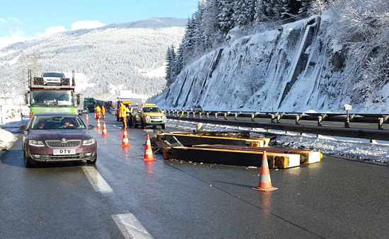
Figure 1a [Aktivnews]
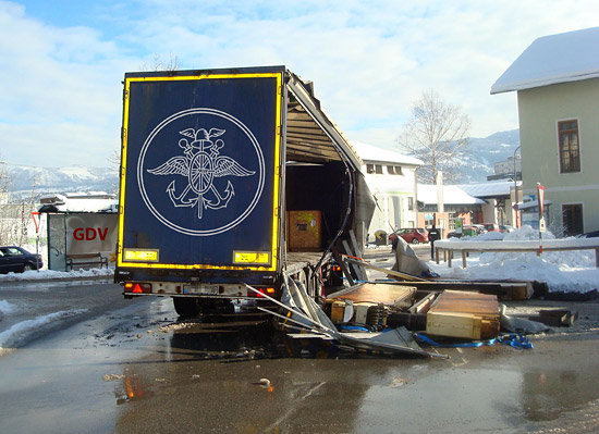
Figure 1b [LVA Salzburg]
Figure 1a shows where the first truck lost its load after joining a motorway. This is clearly not a tight slip road where a 180 ° or 270 ° bend is followed by an acceleration lane. Instead, it appears to be a "gentle" slip road. The load comprised 2 10-tonne veneering presses that fell off to the left into the overtaking lane.
The photo in Figure 1b was taken on the same day and shows a different vehicle with the same load on a roundabout. Here as well, the two 10-tonne veneering presses have broken through the side of the vehicle and dropped onto the road. The truck was on a roundabout, and innumerable examples of accidents with vehicles carrying bottled drinks show that the measures taken to secure the load to the sides are tested to their limits in such situations. It would appear that drivers underestimate the acceleration that acts on the load.
It is no coincidence that the relevant standards and guidelines specify acceleration values of 0.5 g, i.e. half the force of gravity, to the sides and contain special regulations for loads that are liable to tip. Clearly, little thought was given to how susceptible these loads were to tipping.
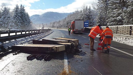
Figure 2a [Aktivnews]
Figure 2a shows the veneering presses lying in the overtaking lane. A steel construction can be seen protruding from underneath the press in the foreground. It is made up of 4 I-beams that have probably been welded together. Because we were not present and have been unable to speak to the company that loaded the vehicles, what follows is conjecture, and we are happy to be corrected.
We assume that these steel frames are cradles in which the presses were inserted in order to increase the footprint of the cargo. Although this approach is fundamentally sound, its effect was clearly inadequate. We have no information as to whether similar cradles were fitted to the top of the veneering presses in an attempt to stabilize the load. The small number of cradle fragments that can be seen in the photos leads us to conclude that this was probably not the case. (End of conjecture).
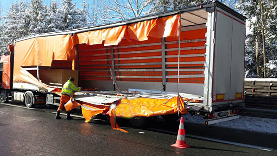
Figure 3a [Aktivnews]
The presses, with a height of 1.20 to 1.30 m and a length of between 5 and 6 m were loaded upright, alongside each other on a curtainsider with side walls. In principle, the vehicle appears to be very new and gives the impression of being well cared-for and stable, which is what we want to see. Unfortunately,because the load had been placed in the middle of the loading area and was only lashed down with 2 belts, the stability of the bodywork could not be exploited for the purposes of securing the load.
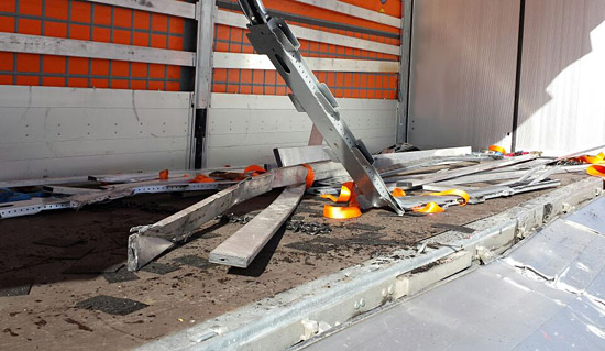
Figure 4a [Aktivnews]
Once a load starts moving, it gathers momentum with each centimeter (no matter whether it is tipping or slipping). If this kinetic energy meets a rigid object, such as a side wall, it is (partially) converted into work, resulting in deformation or destruction. The considerable deformation to be seen on the removable slats of the destroyed side wall, which has been partly pulled from its hinges, not to mention the torn-off stanchion, gives a good idea of the forces that were unleashed.
The only positive thing to say about the way in which this cargo was loaded is that anti-slip mats were used. But the thickness of the anti-slip mats (probably around 3 mm to allow them to be used on a vehicle with Joloda tracks) and the fact that they are not fully-vulcanized, heavy-duty mats, are enough to show that they were more decorative than a serious attempt to secure the load.
Part of a short-link chain is lying right in the middle of the loading area. This chain does not give the impression that it belongs to any of the load-securing equipment. Perhaps an attempt was made to give some kind of support to the load-securing arrangements or to the cradles.
Figure 2b takes us back to the roundabout:
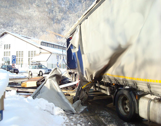
Figure 2b [LVA Salzburg]
The position of the vehicle suggests the circular movement and the direction in which the veneering presses were thrown from the vehicle seems logical. The distorted rear stanchion of the vehicle can be clearly seen in Figures 1b and 2b. The fact that it is not only the bottom of the stanchion, but also the top third that has been deformed is further evidence that the presses had been loaded next to each other. A construction made of I-beams was also found at the scene of this accident, which lends weight to the cradle theory. We are not able to say how these might of been used, as there are a number of possibilities.
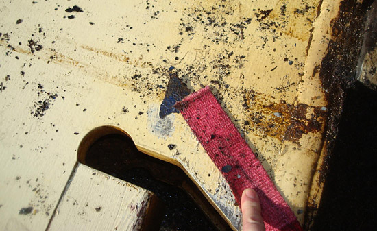
Figure 3b [LVA Salzburg]
The rust spots indicate that the presses were used machine tools, and the fact that the point at which the belt failed is so clean that it looks as if it had been cut with a knife leads us to assume that the load must have had sharp edges.
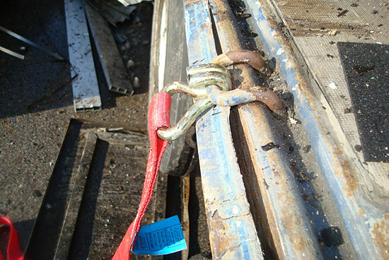
Figure 4b [LVA Salzburg]
During its excursion onto the road, the load bent the load-securing point outwards, although it would originally have been bent slightly inwards, if at all. This is a further demonstration of the considerable kinetic energy involved.
Summary:
The fact that the way in which the cargo had been loaded resulted in lost loads twice in one day shows that the loaders, drivers and carriers were clueless in respect of load-securing. This cluelessness represents a considerable risk to the lives of other road users, no matter whether it be a pedestrian who happens to be standing at a roundabout or an overtaking car or truck freeing up the right-hand lane to allow the truck with the unsecured load to join the motorway. This twofold Photo of the Month shows the monumental irresponsibility of putting such heavy, demanding loads on the roads with absolutely no knowledge of load-securing.
So how can loads such as this be transported safely?
In order to reduce the risk of tipping, it makes sense to use cradles that bundle the components of the load together securely at the top and bottom. If this is not possible, an A-frame would be a good alternative for transporting the load. It goes without saying that loads such as this must not be secured with tie-down lashings. When dealing with weights such as these, direct lashings represent a sensible way of securing the load.
Because these loads were transported in pairs, the option of using A-frames is an obvious choice. These A-frames can be placed on heavy-duty anti-slip mats on the loading surface and should themselves be padded or fitted with robust anti-slip material (heavy-duty anti-slip mats) at the points of contact with the load.
Depending on how stable the A-frame itself is, it makes sense to secure the presses directly to the A-frame. However, we recommend that the load and the A-frame are secured jointly. We would thus recommend at least 3 loop lashings on each side to secure the load to the sides. The important thing here is that each belt is attached to a free load-securing point. Given a load weight of 20 tonnes and assuming that anti-slip material has been used correctly everywhere, 4000 daN of securing force is still required longitudinally. And for this we also recommend at least 2 loop lashings. In principle, a belt can provide a securing force of 4000 daN. However, the angles that arise as a result of the arrangement of the direct lashings cause the securing effect to be distributed geometrically, meaning that a second belt is absolutely necessary.
If the stability of the anti-slip mats used is questionable or if the stability of the A- frame itself is in doubt, the way in which the A-frame is secured to the front and rear must be considerably improved. You will not find any recommendations covering such circumstances in any of the standards. It is purely a matter of common sense. Because your columnists have actually seen A-frames that have simply been put together loosely and where the bearing members are so thin that it would not have been possible to place any anti-slip material on them in any meaningful way, we would assume a coefficient of friction of 0.2 in such cases. This would result in a longitudinal securing force of 12,000 daN, which could be achieved with 4 loop lashings.
The challenge here is to ensure that the loop lashings are arranged in such a way that they cannot slip from the A-frame or the load and that they are all of the same length.
A brief explanation: Direct lashings only generate their securing effect when the load is able to slip slightly into the load-securing equipment. Only then does the load-securing equipment stretch, which releases the considerable direct-securing forces. If one of the belts were shorter than the others, this would fail first, followed by the next shortest belt and so on. If all the belts are of the same length, they are loaded evenly and are able to restrain the load. Edge protection is absolutely crucial in this context.
A further problem can arise when the load protrudes significantly beyond the A-frame, as it is the load that has the weight. If the load is to be secured directly, additional securing of the A-frame is both possible and sensible. If the geometry of the load does not allow the A-frame to be secured, the load should be secured to the A-frame with 2 additional bundling straps. The load must be secured to the rear in the same way.
We wish you a safe journey!
Your Load Securing Team
Back to beginning