
| Photo of the month – November 2013 |
[German version] |
Aftershock
In a similar vein to our Photo of the Month from April 2013, we are again looking at concrete girders.
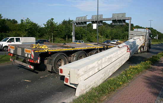
Figure 1 [Press Office of the Dresden police force]
Figure 1 clearly shows that the concrete girders, weighing 11 tons each, were loaded with their center of gravity to the top.
When we looked at the Photo of the Month from April 2013, we had to think long and hard before we assumed that it was only possible for the girders to be loaded with the center of gravity to the bottom. But we have now found out that we were wrong. A kind reader of this column has now pointed out to us that girders like this are always loaded with the center of gravity to the top, because it would otherwise be impossible to place them on the building supports on site. The issue with respect to the center of gravity is well known, but construction sites do not offer any facilities for turning the girders over.
A load such as this, with its center of gravity to the top, poses a particular challenge in respect of securing the load. The problem is that as well as actually securing the load, it is also necessary to take appropriate measures to counteract its lack of stability.
The story of this mishap is quickly told: The truck turned off or changed direction, which caused the girders to part company from the vehicle, falling off to one side.
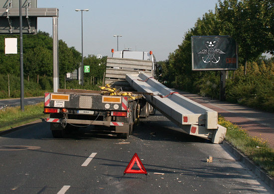
Figure 2 [Press Office of the Dresden police force]
The driver and/or loader had actually given some consideration to securing the load. The use of sandwich elements clearly indicates this (see Figure 3). When we refer to "sandwich elements", we mean that anti-slip material has been placed both underneath and on top of the squared lumber. This means that the friction chain between the load and the loading surface is unbroken.
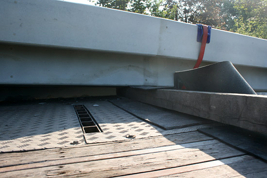
Figure 3 [Press Office of the Dresden police force]
We can actually use a coefficient of friction of 0.6 in our calculations. Unfortunately, as so often, we have to qualify our praise: Once again, at least some of the dunnage used appears to have a square cross-section. And we cannot say with any certainty whether these mats are completely vulcanized and suitable for heavy-duty use. If the mats are not completely vulcanized, but are little more than "placemats", the sheer weight of the load could result in pressures that would completely destroy the lightweight mats on the relatively small contact areas with the dunnage.
Figure 4 below shows the front, left side of the loading surface, and the end wall can just be seen on the far left of the photograph. Once again, tie-down lashings were chosen to secure the load. The position of the girders clearly indicates that they tipped to one side. No anti-slip mat in the world will stop a load from tipping.
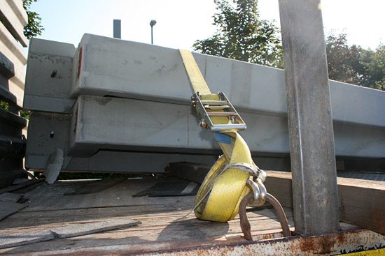
Figure 4 [Press Office of the Dresden police force]
These top-heavy girders are probably also "pre-tensioned", meaning that they are slightly curved, which will slightly increase their tendency to tip to the side. Appropriate measures to counteract this must be taken when securing the load.
Regular readers of this column will undoubtedly already have guessed that we recommend a loop lashing. To do this, the belts are attached on both sides, taken round the girders and back to the side they started on. This is a direct securing method in the literal sense.
To prevent the girders from damaging each other while nevertheless preventing them from tipping, spacers have to be placed on the top crosspiece of the girders and at the bottom between the vertical elements. If rectangular cross-section dunnage is not used, two pieces of square dunnage should be bolted together in such a way that they form rectangular dunnage. Squared lumber is then secured to the top of this dunnage to keep the bottom edges of the girders apart.
If the tops of the girders are also sensitive (which we must assume), spacers must also be used here. This can be achieved relatively easily for the top by nailing two or three pieces of squared lumber (e.g. 10 cm thick) of equal length to a board. This board is then placed on top of the girders in such a way that the spacer falls between the girders. This diagram illustrates this construction:
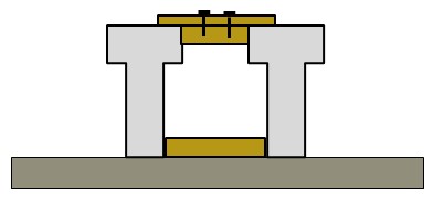
The width of the top and bottom spacers must be such that the girders are as nearly vertical as possible. If it is not possible to place the side loop lashings in such a way that they also secure the top spacers, each of the individual top spacers should be secured with an extra tie-down lashing to make sure that it cannot slip or drop out.
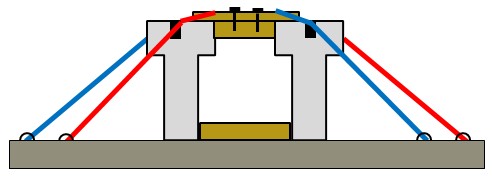
Figure 5 clearly shows how the sideways movement of the concrete girders gradually transformed the tie-down lashings into direct lashings. It would have been better to achieve this direct securing effect to start with. Four loop lashings on each side are needed to secure the unstable girders to the sides. It is, of course, necessary to take particular care that the direct lashings are arranged correctly and that edge protectors are used. All the direct lashings should if possible be of the same length and protected against the sharp concrete edges.
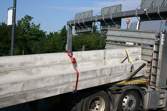
Figure 5 [Press Office of the Dresden police force]
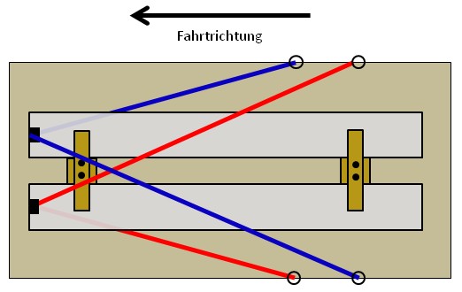
The high level of friction provided by the anti-slip mats is fully utilized when securing the load in the direction of travel. With a coefficient of friction of 0.6 (when rectangular sandwich elements are used as dunnage), it is only necessary to secure 0.2x the weight force of 22,000 daN. This remaining securing force of 4,400 daN can be achieved with two belts or suitable chains. The best way of doing this is to pass the two direct lashings crosswise over the ends of the girders and secure each to the opposite side. Here also, edge protectors must be used. This diagram provides a top view illustrating the principle:
And here is the side view, in which we have only shown one of the two belts for the sake of clarity:
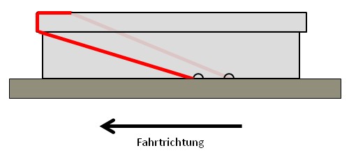
Because direct lashings only deliver their full lashing capacity (LC) when the belt or chain is stretched to its limit, the pre-tensioning force should be as high as possible up to a maximum of 50%. This high pre-tensioning force minimizes the distance that the concrete girders need to slip before the direct lashings are tensioned up to their LC.
Your load securing columnists thank all those who have given us practical advice and help. Despite the incorrect assumption with respect to the position of the center of gravity, we shall not change our Photo of the Month from April, because it remains a useful guide for similar loads.
We wish you and your load a safe and secure journey.
Your Load Securing Team
Back to beginning