
| Photo of the month – October 2013 |
[German version] |
Lord of the rings?
The massive bulge in the tarpaulin that can be seen on this photo gives rise to the justified impression that the cargo on this vehicle was eager to escape:
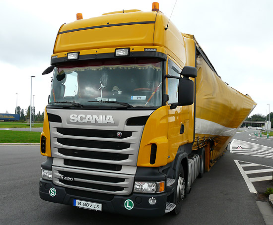
Figure 1 [Raymond Lausberg]
And the following photos only confirm this impression. A large cylinder or ring is leaning against the curtain of a double drop deck trailer:
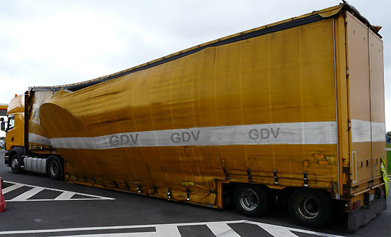
Figure 2 [Raymond Lausberg]
Figure 3 shows exactly what's going on. The load is made up of large steel rings, which were originally standing on edge and leaning inwards against an A-frame. A car cut in in front of the truck and the driver had to take avoiding action and brake hard to prevent a collision:
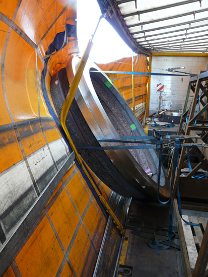
Figure 3 [Raymond Lausberg]
As a consequence, the load-securing measures failed, the rings rolled forwards and collided with the step of the drop deck trailer. After this collision, the rings fell into the tarpaulin, which "restrained" them.
It could be claimed that the car driver was to blame for the fact that the load slipped, rolled and tipped. Although he caused the truck to break heavily and is responsible for the damage, inadequate load securing is to blame, because loads must be secured on a truck in such a way that they are able to cope with precisely this kind of emergency situation.
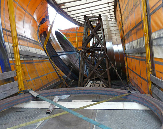
Figure 4 [Raymond Lausberg]
This load is, in fact, rather special.
- The steel rings were transported upright in an A-frame. One of the rings was an exception in that it was transported on its side.
- The trailer is a double drop deck trailer, and the only reason for using it was that the steel rings were intended to be transported upright in the A-frame, which would have made them too high to be transported on a normal trailer.
- Clearly, the load had been secured using load-securing equipment.
So what was wrong?
We shall use a drawing to help explain, because it is clearer than the photos of the actual accident. The rectangular frame on the drawing is intended to represent the A-frame. The A-frame was standing on anti-slip mats and was secured to the double drop deck trailer using chains in a direct securing arrangement. As far as we understand, the A-frame did not move, or if it did, only did so minimally. The steel rings were placed upright against the A-frame. The A-frame comprised only the two sides of the "A". There was no base on which the load could be placed (such as those seen when transporting glass, for instance).
The rings weighed a total of 18.5 t. Because there were a total of nine rings on the vehicle (four on each side of the A-frame and a larger ring on its side behind the A-frame), we can, for the purposes of our calculations, assume that each ring weighed 2 t. This means that 8 t were resting on each side of the A-frame, making a total of 16 t.
The original load-securing measures:
The blue lines on the diagram in Figure 5 show the way in which the load was originally secured. The diagonal lines at 4 o'clock and 8 o'clock represent loop lashings and the straight line from 12 o'clock to 6 o'clock represents a tie-down lashing. After the accident, the driver also explained that he had used anti-slip mats under the steel rings.
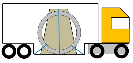
Figure 5 [GDV]
Assessment of the original securing arrangement:
The A-frame was standing on anti-slip mats and was secured by means of direct lashings (chains). Unfortunately, we do not know the LC of the chains and of the load securing points that were used. We assume that the standard 2000 daN load securing points were available. This securing arrangement was adequate to secure the A-frame.
The steel rings were secured by a tie-down lashing and one loop lashing to the front and one to the back. The crucial thing in this situation is that the rings must be secured against rolling in a longitudinal direction, because friction has a negligible effect here. Rolling friction can be assumed to have a magnitude of one fiftieth. In other words, it can be completely ignored when calculating the load securing measures. Ultimately, this means that in the longitudinal direction the securing force must correspond to 0.5 of the mass of the load to the rear and 0.8 of the mass of the load to the front.
In fact, the 8 x 2 t, i.e. 16 t, load of steel rings was secured with just a single loop lashing in each direction, which was clearly inadequate. The loop lashings shown in the diagram are able to provide twice the lashing capacity. In other words, the rings were secured with 4000 daN (we have ignored the angles in making this assumption). But because the friction is negligible, they should have been secured with a securing force of 12,800 daN.
This means that at least four belts should have been used to secure the load to the front and at least two to secure it to the rear (16 x 0.5 = 8, resulting in a required securing force to the rear of 8000 daN.
Because the angles between the load securing equipment and the load itself always "weaken" the securing equipment or, more precisely, have a negative impact on the restraining force of the belts in the intended direction, two belts are not sufficient in this case, because 2 x 4 is exactly 8, which does not allow any safety margin for angles. Which means that a third belt must be used:
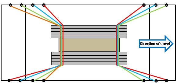
Figure 6 [GDV]
Movement of the load:
At this point, we would like to take a few moments to discuss the theory behind load movement. Let us look at the question of the precise time at which the belt delivers its full lashing capacity. This only happens when the belts are fully loaded. But belts only become fully loaded when they have stretched by the amount specified on the label (e.g. 4%) when a load is applied.
What this in effect means is that if a belt with a total length of 4 m is passed through the rings, it must stretch by a distance of 16 cm. Because the belt is attached to both sides of the vehicle and runs to the rear, these 16 cm are divided between the two sides. Furthermore, the fact that the belt has been pre-tensioned has already taken up 1% of the stretch. This means that the 8 cm is reduced by a further 1 or 2 cm.
But the fact remains that the rings must roll or slip forwards by at least 6 cm before the belt delivers its full lashing capacity. For this reason alone, it borders on criminal negligence to calculate so tightly that only 2 belts are used to deliver 8000 daN of securing force. It is absolutely necessary for a third belt to be used here.
Another problem that we have already mentioned in other Photos of the Month is that multiple belts that are all intended to act simultaneously in the same direction must all be of the same length. This can be achieved by offsetting the belts, but this may cause problems in that the belts must effectively all be passed through the same point on the rings or that the curvature of the rings causes them to slip to the same point. In this case, it is worth considering securing the load with a direct lashing using chains with a lashing capacity of, e.g., 10,000 daN. Of course, if this is to be done, it is necessary to have the appropriate load securing points and to use edge protectors to protect the load from the chain and vice versa. These would have to be special steel protectors for chains, but these are available commercially. It goes without saying that belts should always only be used with appropriate edge protectors.
The original securing to the side:
After the single belt that was used to secure the load in the direction of travel had failed, the rings rolled forwards a little, hit the front step of the drop deck trailer and tipped to the side. The rings rolled out from under the tie-down lashing that had been used. This clearly shows the extent to which the load is liable to tip.
Securing:
One approach to eliminating this tendency to tip would be to bundle the rings and connect them directly to the A-frame with direct lashings. This can, of course, be done in addition. But we recommend a total of 4 loop lashings. These are placed through the rings at the front to both sides and through the rings to the back at both sides. This not only secures the rings to the sides, but also presses them against the A-frame. To prevent the rings from tipping away from each other at the top we recommend that you bundle the two stacks of rings together (in the center at the top) with a belt.
At this point, we would like to turn our attention briefly to the ring that was carried on its side. One positive aspect is that protective sleeves were used for the belts. Another praiseworthy aspect is that generous amounts of anti-slip material had been laid out on top of the squared lumber and we simply assume that there were also anti-slip mats under the squared lumber. The load was secured with two tie-down lashings. The angles of the tie-down lashings were around 30°, which means that 50% of the overall securing effect of the tie-down lashings was lost as a result of the angles. We also assume that this ring weighed just 2 t. This means that 1,600 daN securing force to the front would be required. If anti-slip mats were used everywhere, we can assume a coefficient of friction of 0.6. This means that a total of 400 daN securing force is still required. Because the angles are so poor, 1334 daN of pre-tensioning force need to be applied rather than just 667 daN. This begs the question why four direct lashings were not used to secure a load such as this. Admittedly, you need four direct lashings instead of two tie-down lashings, but the securing effect would, as is so often the case, have been far better and it is possible to pre-tension the direct lashings in such a way that a small part of this force has the same effect as a tie-down lashing.
Closing comments:
In principle, those responsible for loading this vehicle gave some thought to securing the load. The A-frame was placed on anti-slip mats and secured well to the front and rear with direct lashings. The ring on its side was placed on lumber which (we hope) was in turn resting on sandwich elements made from anti-slip material and lumber. The belts that were used were protected correctly, but there was a complete absence of thought when it came to securing the steel rings on the A-frame. Rings are round and, unsurprisingly, tend to roll, which means that a force equivalent to 80% of their weight must be applied to secure them. The anti-slip mats placed under the load only have any effect in securing the load to the side, and not longitudinally.
The high weight requires a large number of belts. This large number of belts (four to prevent forward movement) must all be of the same length so that they are all loaded at the same time. The choice is either to work very carefully using offset belts (see the diagram in Figure 6) or to use very strong load securing equipment, which in turn requires load securing points that are equally strong. If you choose to work with offset belts, they must not only have protective sleeves, but also edge protectors to allow the belts to slip under load. If you then take steps to prevent the rings from tipping, it is possible to lord it over these rings.
Your load securing columnists wish you all a safe journey every time!
Back to beginning