
| Photo of the month – September 2013 |
[German version] |
Stopped in its tracks
An articulated truck with a standard trailer had to slow down from 50 kph near roadworks. In Figure 1, we can see that the rear of the trailer is rather higher than it should be, which would lead us to assume that little notice was taken of the load distribution plan during loading:
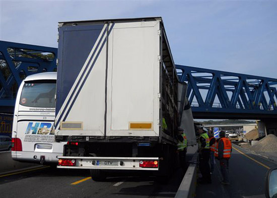
Figure 1 [Christoph Gontermann]
Figure 2 makes us revise this assumption, and suggests that we are dealing with a more serious problem. The bend in the trailer has forced the two ends upwards and pushed the middle down considerably:
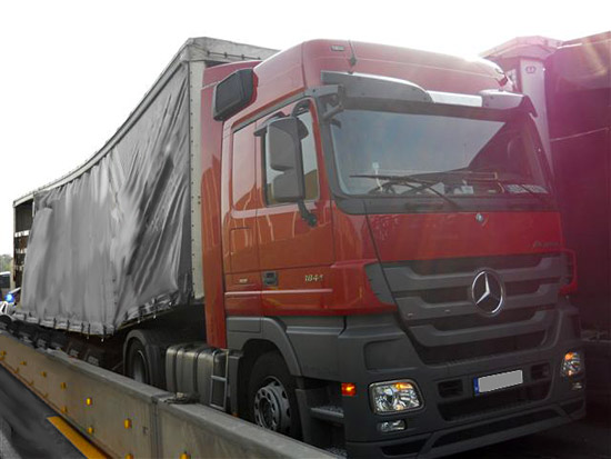
Figure 2 [Christoph Gontermann]
Figure 3 shows that the vehicle has literally broken its back. The longitudinal members of the vehicle have either mostly broken or have been bent sideways. The entire vehicle frame has sagged dramatically so that the retracted trailer legs and the pallet boxes are resting on the road. This happened while the vehicle was still moving, as can be clearly seen by the "skid marks" of the legs on the road surface.
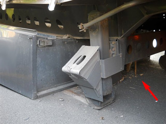
Figure 3 [Christoph Gontermann]
In addition, if you look carefully, you can see parts of the bed of the vehicle behind the left-hand leg. The fragments and other sections of the bed of the vehicle (see arrow) that can be seen further behind give a clear impression of the massive force that must have acted on the bed. If we exclude the possibility of a meteor strike (which is unlikely, as the tarpaulin is undamaged), it must have been the load that generated these huge forces for some reason.
The load itself is a cylindrical steel component. This cylinder was standing on a strong, specially built pallet. We can assume that this pallet was necessary, because the 23 t cylinder would probably have been loaded by forklift truck. It is almost certain that the position of the load was chosen by consulting the load distribution plan (or purely by intuition):
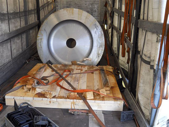
Figure 4 [Christoph Gontermann]
2 longitudinal wooden supports for the cylinder had been attached to the pallet itself. 5 wedges were nailed behind the load in a semicircle to secure it. A similar semicircle of wedges was also nailed in front of the cylinder. This can still be clearly seen from the remaining fragments of the wedges. The load was secured with four tie-down lashings.
Despite being easy to attach, tie-down lashings have their limitations. As we have often written in this column, the unrivaled advantages of tie-down lashings are that they use friction to act in all directions and are very effective and easy to use for relatively light loads.
An excellent level of friction is necessary if a tie-down lashing is to be effective. In this case, however, the steel cylinder was loaded directly onto wood. When the vehicle slowed down, the cylinder slipped forward along the longitudinal wooden supports, removing the five wedges (which were, incidentally, cut incorrectly), slipped from the pallet and impacted with the trailer bed, which it then probably broke through, with its bottom, front edge. When the front edge penetrated the trailer bed, the cylinder was prevented from moving any further:
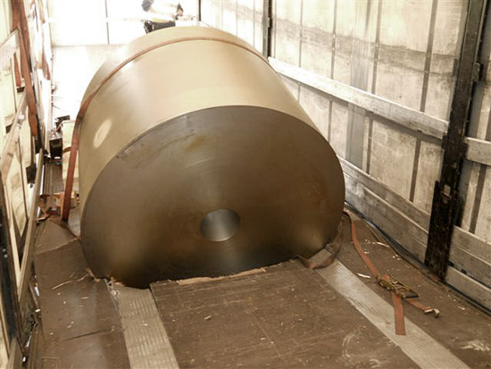
Figure 5 [Christoph Gontermann]
Because the cylinder still had sufficient kinetic energy relative to the loading surface, it tipped forward by something like 110 degrees around this unexpected blocking. Its top, front edge hit the bed and broke the back of the trailer. Ultimately, the movement under the tie-down lashing produced a tight fit:
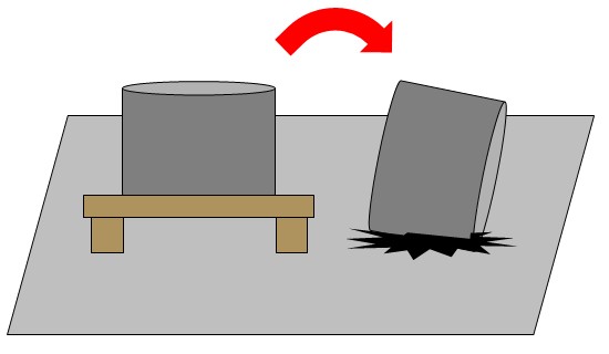
Figure 6 [GDV]
Forgive us if we are a little sarcastic. Specialists in the field frequently talk about "motion locking", which is in itself a self-contradictory concept that it is impossible to resolve. It is quite alarming to remember that the vehicle was merely breaking to slow down. If the vehicle had taken perfectly normal avoiding action, perhaps coupled with similar braking, this 23 t cylinder would have dropped onto the road and buried anything traveling alongside it or coming towards it.
So how can construction parts like this be secured effectively?
In principle, the pallet is well-built. It appears to be stable and seems to have suffered no damage during loading. If you want to secure a load like this to the pallet as a tight fit (and the wedges indicate that this was intended), heavy wooden beams must be bolted onto each side. The bolts must pass through the bearing members of the pallet, and lock nuts must be used. The bolts themselves must be strong enough to withstand the shear forces resulting from acceleration:
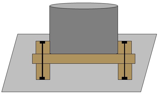
Figure 7 [GDV]
The points of contact between the load and the pallet must be covered with heavy-duty mats (completely vulcanized to prevent them from crumbling). And, of course, all points of contact between the pallet and the bed of the vehicle must be covered with anti-slip mats. Figure 4 shows some anti-slip mats under the palette. In order to ensure that the pallet, and hence the load, is completely isolated from the bed of the vehicle in terms of friction, it is necessary either to place under the pallet anti-slip mats which are thick enough to ensure that the pallet is physically separated from the bed, or to place appropriate anti-slip material under the entire surface of each of the skids.
If the load is now secured with tie-down lashings, one can assume a coefficient of friction μ of 0.6. But, at a weight of 23 t, 7,667 daN pre-tensioning force is still required to secure the load adequately. This will be difficult, not least because there are not sufficient load-securing points in the vicinity of the load.
We recommend a mixture of direct lashings and tie-down lashings. Let us first deal with the tie-down lashings, which are intended to suppress oscillation and vibrations to ensure that the high level of friction will always act in any driving situation. To achieve this, we would recommend 2 tie-down lashings placed diagonally over the cylinder. It is, of course, necessary to protect the belts from the sharp edges of the cylinder. These tie-down lashings take care of securing to the sides and to the rear:
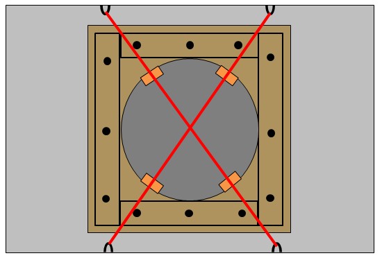
Figure 8 [GDV]
We still have to find 4,600 daN of securing force to the front. This can be achieved using just 2 belts. We are assuming that it is not possible to pass any securing equipment through the eye of the cylinder. This presents us with the problem of fitting load-securing points to a cylindrical load. This can be done by placing a lifting sling over the top, front edge of the cylinder. It is then no problem to attach 2 belts to this lifting sling. These are doubled back and attached to 2 different load-securing points (on each side) to the rear:
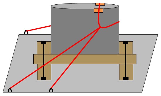
Figure 9 [GDV]
Considerable pre-tensioning force should be applied to these direct lashings, because direct lashings only generate additional load-securing forces when they are stretched. In other words, the load has to slip or tilt. Only when the load-securing equipment is subject to elastic deformation up to its rated stretch limit does it deliver its rated lashing capacity (LC). The advantage of this particular securing arrangement is that the entire pre-tensioning force is already acting against the expected direction of motion, without any direct lashing to the rear acting in the opposite direction and canceling it out (at least when the load is at rest).
We wish you a safe and secure journey.
Your Load Securing Team
Back to beginning