
| Photo of the month – August 2013 |
[German version] |
Let the drums roll
It is somewhat of a platitude to say that the laws of physics always apply everywhere, particularly for any material of any weight. We probably remember our physics teacher drumming into our heads that "to every action there is always an equal and opposite reaction." In other words, whenever a force is applied somewhere, it is not destroyed; instead, something always happens as a reaction.
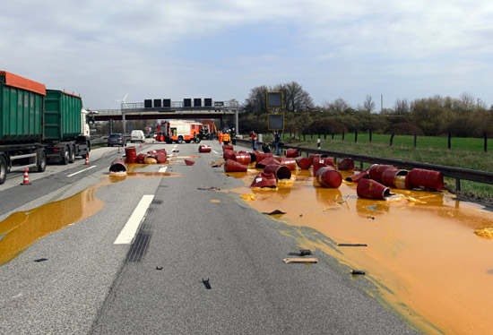
Figure 1 [Reiß]
In this case, an articulated truck with a curtainsider trailer loaded with steel drums filled with orange juice concentrate braked as it approached the end of a traffic queue. The skid marks on the road are plain to see. To cut a long story short: The drums slipped forwards, pushed the curtain apart, fell from the truck on both sides and were bent, with the results that they deposited their sticky, sour contents generously over the autobahn. It was fortunate that there were no cars under the drums and that no other vehicle crashed into this avalanche of drums. But because this column is not content to merely identify damage, but intends to draw lessons from the damage, this Photo of the Month will again be a little longer.

Figure 2 [Reiß]
Figure 2 gives a very good idea of the force with which the drums on the loading area slipped into each other and the force with which they hit the road. In all probability, the weight of each drum was considerably more than 200 kg. If a car had driven into one or two of these drums with the difference in speed of just 80 or 100 km/h, the result would have been a written-off vehicle or even worse.
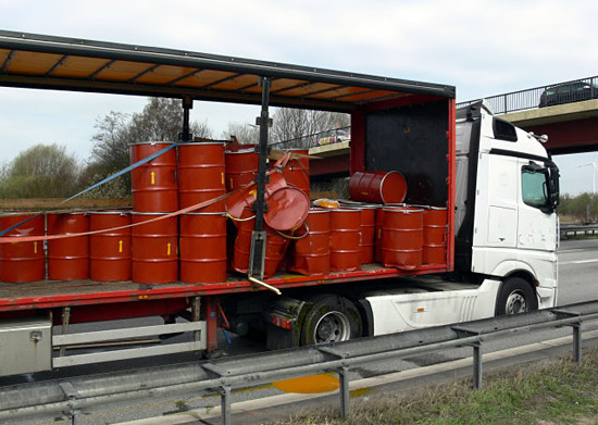
Figure 3 [Reiß]
The drums that remained on the loading area (see Figure 3) echo our words. They tell us that they were originally loaded in two layers. Again, in all probability, the second layer was only loaded towards the rear of the vehicle in order to distribute the load properly. The splinters of the removable boards that can still be seen attached to the collapsible stanchions tell us that the drums effectively caused the vehicle to burst when they slipped into each other. We shall have something to say about the belts and fragments of wood on the top of the drums a little later.

Figure 4 [Reiß]
We have only included Figure 4 in this column so that our readers can envisage the force, or kinetic energy, that was converted to deformation energy in this incident. One of our readers has been kind enough to share one of his favorite examples: During his training courses, he demonstrates that it is possible to place a 2 kg hammer on a sheet of glass without any problems, but that it is simple to shatter the same sheet of glass with a "light", 500 g, hammer from a distance of just 20 cm. As far as this Photo of the Month is concerned, this means that if the drums are actually loaded as a tight fit and are unable to slide in the slightest, it is not possible for them to generate any kinetic energy relative to the loading area that would be able to cause such deformation.
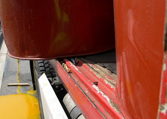
Figure 5 [Reiß]
This picture also has something to say. The drum has become slightly deformed as a result of colliding with its neighbors. The longitudinal member on which the drum appears to be balancing shows the remains of a shattered removable slat, of which another piece can be seen on the road. This drum managed to stay on the vehicle (unlike many of its colleagues).
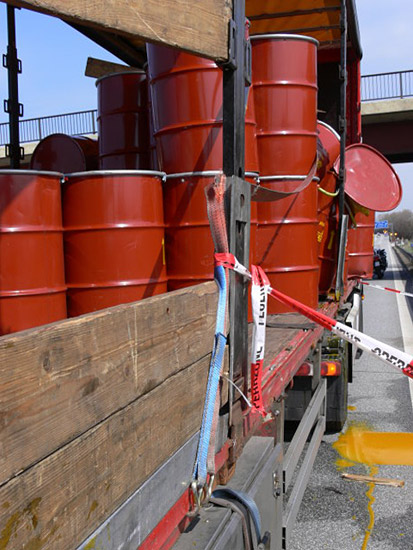
Figure 6 [Reiß]
Figure 6 gives a graphic impression of the way the drums slipped forward up to the point where they parted company with the vehicle. The belts, which were originally placed across the load as tie-down lashings also slipped forward a long way with the drums. But because the load slipped underneath the belts, they were not able to establish any significant securing force, even though they moved with the load, which would normally considerably increase the pre-tensioning force. One of the pictures below will show us exactly why this did not happen.
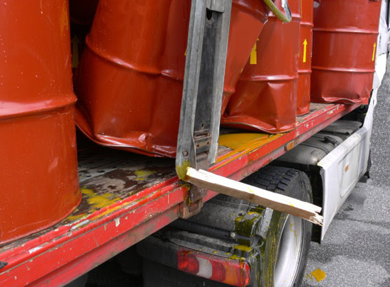
Figure 7 [Reiß]
Figure 7 shows the deformed barrels and is a testament to the considerable amount of energy released during a braking maneuver. The vehicle converts this energy into thermal energy at the brakes, making use of abrasion and the friction of the tires on the road surface. The drums, on the other hand, having far less friction against the loading surface, cannot make use of this "trick". They must adhere to the laws of physics (to every action there is always an equal and opposite reaction) and maintain their speed until friction or something else slows them down or stops them.
The adjustable stanchion is clearly deformed and shows that at least one removable slat, or even two, have given up the ghost here.
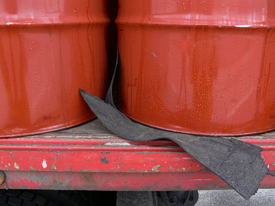
Figure 8 [Reiß]
Figure 8 shows a pretty lousy attempt to increase friction. And if our regular readers are now crying out that we constantly preach that friction should always be increased in order to minimize the effort involved in securing the load, they are absolutely right.
But if an attempt is made to increase friction, then it should be done properly, in such a way that the load is completely isolated from the loading surface in terms of friction. And this means that the load should never, under any circumstances, touch the loading surface, either as a result of a braking maneuver or avoiding action or as a result of any protruding "feet".
So let us take a look at the thin anti-slip mats on this vehicle. How on earth is a 3-mm thick "placemat" expected to withstand the extreme loads exerted by these heavy drums, especially since it is not fully vulcanized, and is therefore not a heavy-duty mat?
In this example, all the forces resulting from a braking maneuver would be concentrated on tiny points towards the front of the drums, and this effect would be exacerbated by the fact that the drums were loaded in two layers. A drum will always tilt slightly and concentrate the weight force towards the front of the rim of the drum, which will then only make contact with the loading surface at certain points. Under these circumstances, a certain amount of slippage is unavoidable, however well the load has been secured.
If, however, each individual drum is standing on a fully vulcanized, heavy-duty mat, thus ensuring that every single drum on the loading area without exception enjoys the benefits of this high level of friction across its entire contact surface, then and only then can you count on the high level of friction.
The person responsible for securing this precise load (i.e. initially the loader, and then, as always, the driver) faced a particular challenge. The drums in this example were loaded in two layers. If drums are loaded in two layers, they only make contact with each other at the rims. As a rule, they are not stacked exactly one on top of the other but will probably sometimes be offset. This means that they only make contact with each other at a limited number of individual points. From this remove, we are unable to assess the magnitude of the pressure on these individual points, but those who know their drums and the way in which they are loaded will undoubtedly be able to do so.
It is absolutely necessary to check whether heavy-duty mats are even available that are able to withstand the point loading that results from drums being stacked on top of each other. If this is not the case, the following approach is recommended in order to distribute the load better and to avoid point loading.
Pallets or walking boards can be used if the drums are to be loaded in two layers. Strong sheets of plywood are suitable for this purpose, as are pallets, preferably Europallets, because these have the advantage of being stable.
Firstly, a friction-enhancing surface comprising heavy-duty mats is placed on the bottom layer of drums so that the plywood sheets or pallets that are then placed on top of this have no friction contact whatsoever to the bottom layer. Another layer of friction-enhancing material is then placed on these pallets or plywood sheets to ensure that the drums loaded on the second layer also benefit from the high level of friction.
Of course, there is also the option of relying only on the friction between the wood and the steel drums. In this case, the load will require far more lashing, because the level of friction is far lower.

Figure 9 [Reiß]
Figure 9 clearly shows how those responsible attempted to secure the load. Of course, the method chosen was tie-down lashings. But by their very nature, round drums are difficult to secure with tie-down lashings. To allow multiple drums to be secured with a single belt, removable slats were placed on the outer edges of the drums. In principle, this is not a bad idea, because the point of the exercise is to distribute the pressure and prevent the belts from slipping off. Sadly, tie-down lashings generate a diagonal, inward force where the belt passes over the edges of the load. As soon as the load begins to move in any way, even as a result of the truck simply moving off, the slats will slide inwards and the lashing belts become loose and have no effect whatsoever. In fact, it is nigh on impossible to do anything more foolish than this.
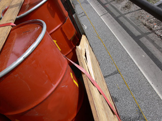
Figure 10 [Reiß]
Figure 10 is a magnificent example of the forces that can be expected in this scenario. After the belts had slipped between the drums, which then continued to make their way forwards, pretty well unhindered, to follow their friends into the big wide world, they took the belt with them for a while. The belt was now transformed from a tie down lashing to a direct lashing and immediately developed a considerable securing effect. This is clearly indicated by the removable slats, which were not pushed outwards, but instead were pushed inwards until they snapped. To every action there is always an equal and opposite reaction.
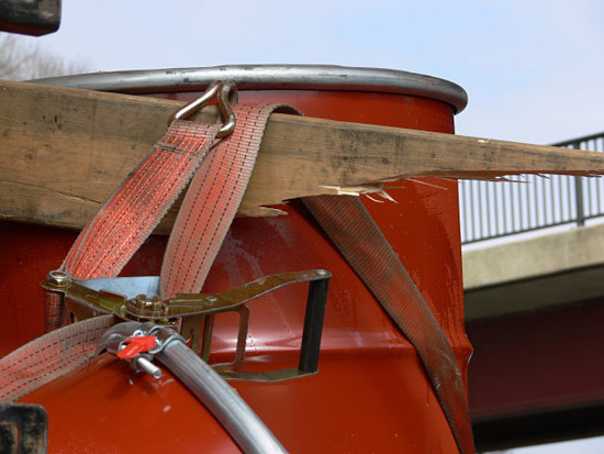
Figure 11 [Reiß]
Figure 11 exemplifies the forces involved and the abject failure of the attempt that was made to lash down this load.
So how can loads like this be secured properly?
As we have already said, strong, fully vulcanized, heavy-duty mats must be arranged in such a way that the entire loading area is completely covered. This must be done in such a way that the drums cannot make contact with the loading surface directly, no matter what loads they are subjected to. The drums must then be loaded as a tight fit, preferably in rank and file as a "soldier stow". Depending on size, it is, of course, also possible to stow the drums in offset rows.
Because it is in practice virtually impossible to stow drums in such a way that they do not create gaps if they slip, it makes sense to divide the loading area into two or even three sections. This can be achieved, for example, by joining two pallets with two or three squared lumber beams to form an artificial end wall, and then securing this to the rear with two belts used as loop lashings. But it is also possible to restrain the drums in a loop (a bight). To do this, two of the middle drums are placed in front of a pallet. The belts are passed through the pallet and the next drums are offset to the side and stowed further behind. This means that these drums can also be restrained when a load is applied without constructing a complex securing arrangement. Nowadays, some manufacturers are already making intermediate walls that are able to withstand considerable loads and which can be used for cargo of this type.
We have already explained how friction can be increased on the second layer. But because the maximum coefficient of friction μ that we can use for calculation is 0.6, no matter what steps we have taken to increase it, the drums on the second layer must also be prevented from slipping forwards. This can also be achieved by an artificial intermediate wall and loop lashings or by appropriate tie-down lashings. Because drums are a particularly complex, difficult load, we always recommend that steps are taken to ensure that friction is acting and is maintained at all times, no matter how high the level of friction is and how stable the superstructure is.
To do this, the drums must first be stowed in such a way that they can be combined to form a load unit using large plastic angle plates. These angle plates must be stable enough to withstand the pressure of the belts even if the drums slip slightly. They must also act on all the drums. The same applies to the drums on the second layer. If the drums on the second layer are to be restrained using tie-down lashings alone (we assume that there are only 40 drums in the second layer, i.e. a weight of 8 t), 1600 daN of securing force is still required. This still means that the total pre-tensioning force required is still 2667 daN. This could easily mean 6 belts for the second layer alone.
And we still have to remember to secure the bottom layer. Because drums almost always behave differently from what we expect and a certain amount of movement within a load block is always possible, particularly if the block is made up of heavy drums, direct lashings should always be used to prevent the load from slipping forwards if it is stowed in two layers. Even if the relevant guidelines do not urgently recommend this course of action, common sense and an instinct for load securing should make it obvious.
Your load securing columnists hope that this rather detailed example has given you plenty of food for thought, particularly for any loads of drums you may have. Perhaps we should at this point mention that plastic drums can be just as heavy as the steel drums in this example, but have even more unpleasant surprises in store, because they are much more flexible than steel drums. But we shall look at that another time.
Back to beginning