
| Photo of the month – July 2013 |
[German version] |
Steel: the same old story
It is strange how heavy loads so often seem to slip and cause serious damage. Here again, the load has slipped. In this case, it is steel beams with a weight of 24 tonnes.
The driver of the articulated truck was driving along the freeway at around 50 km/h when he came up behind a queue of traffic. He had to carry out an emergency braking maneuver to bring his truck to a standstill.
At this time, his load, unsurprisingly, was traveling at the same speed. The driver managed to get his truck to "outbrake" the steel beams to a certain extent. Anyone reading this page can undoubtedly imagine that this was not his intention.

Figure 1 [Martin Vollmer]
As can be seen in Figure 1, the load of steel has slipped a little more than a meter forward off the trailer. Even the end wall could not prevent this. Parts of the end wall wrapped themselves around the front of the steel bundles like a cuff.
So much for the claim that "my end wall will withstand five tonnes."
But perhaps the end wall really is able to withstand that much under certain conditions. But more of that later.
The steel did not come to a rest until it was packed tight against the driver’s cab, as you can see from Figure 2 (on the first two pictures, the tractor unit had already been pulled forward a little).
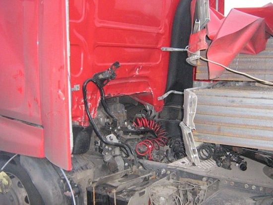
Figure 2 [Martin Vollmer]
All the supply lines to the trailer were ripped off.
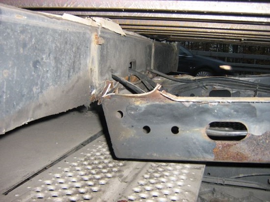
Figure 3 [Martin Vollmer]
Part of the front frame of the trailer had even been torn off.
Let us have a look at the load on the loading surface:
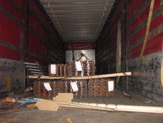
Figure 4 [Martin Vollmer]
The load is made up of five bundles of I-beams. Each bundle has been strapped together with steel straps to form a load unit.
Three bundles have been placed on squared lumber directly on the loading surface, which was made of screen-printed wooden laminate. The remaining two bundles were placed on top, also on squared lumber. No friction-enhancing mats can be seen on any of the photos.
As can be seen from the marks on the loading surface caused when the load slipped, it had been loaded around 50 cm behind the end wall. This means that the was no tight fit to the front.
Neither was there a tight fit to the sides. There was a gap of around 60 cm to each side and to the rear.
The driver chose to secure the load with tie-down lashings. To do this, he used a total of five lashing belts tensioned using short-lever ratchet tensioners.
He is reported to have said to the police: "Each of the belts will withstand five tonnes. That should be plenty for my load."
Unfortunately, a symbol rather like an inverted "U" still appears on many belts. Below this symbol, we see "5,000 daN". This symbol is intended to indicate that a doubled belt that provides 2500 daN of securing force when subjected to a load in a straight line will hold 5000 daN. Of course, this only applies if the load-securing points also each have a capacity of 2500 daN (which is rarely the case) and if the belt is used as a direct lashing. A tie-down lashing, however, only acts as a direct lashing to prevent the load from flying upwards. But this is not the type of securing we are looking for here. And so, the effectiveness of this type of securing derives from the pre-tensioning force applied manually, and even then only in combination with friction. Unfortunately, this is often the cause of such false assumptions, and a corresponding lack of understanding.
The photos already provide a clue as to the securing effect that can be achieved by these tie-down lashings. So it is once again time to point out how much securing false lashing belts can actually deliver, even if they are tensioned under very particular conditions.
Securing force from a lashing belt in a tie-down lashing:
Pre-tensioning forces are introduced into the lashing belts that approximate to the specifications on the label of the belt. On the label, they are shown as the STF (Standard Tension Force, i.e. the pre-tensioning force that can be achieved).
Let us assume that a lashing belt has an STF of 350 daN (this is a realistic value for a belt with a short-lever ratchet tensioner). In this case, this is the amount of pre-tensioning force that a user can introduce into the lashing belt using the ratchet tensioner (the value may be a little more or less depending on the strength of the user).
Part of this force (approximately half) is transmitted to the other side of the load. This gives a total pre-tensioning force in the belt of 1.5 x 350 daN. This amounts to 525 daN.
How much of this pre-tensioning force is actually able to act on the load as securing force depends on the angles at which the lashing belt has been tensioned and the friction between the load and the loading surface.
Let us assume that the lashing belt has been tensioned at an ideal angle between 90° and 60° and that the coefficient of friction μ is approximately 0.3 (steel with mill scale and some rust on wood, as in this case). We now have to multiply the pre-tensioning force by the coefficient of dynamic friction to get the actual securing force.
525 x 0.3 = 157.5 daN.
In other words, under ideal conditions, this lashing belt would deliver a securing force of just under 160 daN.
The load on this photo weighs 24,000 kg. To adequately secure this load to the front, a securing force of 80% of the weight of the load, i.e. 19,200 daN needs to be provided. Because we are assuming a coefficient of friction μ of 0.3, we already have securing forces amounting to 0.3 x 24,000 = 7200 daN. We can subtract these forces from the total securing force required:
19,200 – 7200 = 12,000 daN.
The shortfall in securing force of 12,000 daN now has to be provided by the lashing belts. If all belts deliver a securing force of just under 160 daN as described above, we still need 75 lashing belts to adequately secure the load against slipping.
This begs the question of whether there is another solution to the problem.
And there is.
To start with, we have to increase the friction. If anti-slip mats are used, we get a coefficient of friction μ of 0.6 provided that the loading surface is clean and the mats are in good condition. It is vital that the anti-slip material is fully vulcanized with a high compressive load capacity per unit area, because the I-beams have an extremely narrow contact area and therefore exert an extremely high pressure on the loading surface or the mat. If normal anti-slip mats are used, there is a risk of them being destroyed, and this would be counterproductive.
This measure alone provides a securing force of 14,400 daN. The shortfall of 4800 daN would, however, still require 16 lashing belts, which is far too many.
If the cargo was loaded hard against the end wall without any gaps in the load, and steps were also taken to ensure that the pressure was distributed evenly over the end wall, then the end wall would in this case provide 5000 daN of securing force (provided that it is not damaged). This alone is sufficient to secure the load to the front if steps are taken to maintain the friction everywhere.
Lashing belts can be used to achieve this. Given a load length of around 12 meters, four lashing belts should be enough. The use of these belts in conjunction with the coefficient of friction μ of 0.6 automatically meets the requirements for securing the load to the sides and to the rear as well.
If, however, the cargo must be loaded further to the rear in order to ensure that the load is distributed correctly, which was clearly the case here, an artificial end wall must be built in front of the cargo in order to restrain it when it is subject to acceleration forces.
The photograph below shows what a wall like this could look like:
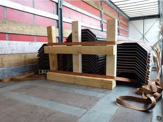
Figure 5 [Wolfgang Jaspers]
In this example, five pieces of squared lumber were joined together and placed in front of the load. A lashing belt was attached to the top and bottom of this "artificial end wall" and each belt was tensioned to the rear on both sides. This is a method that uses direct securing, in which the belt delivers considerably more force than is the case with a tie-down lashing. In this configuration, the lashing capacity LC (in a straight line) for each side is the significant value, and this can be found on the label of the lashing belt as described above. With the belts used here, this should be around 2500 daN. But because the lashing points only have a capacity of 2000 daN, the securing force is also limited to 2000 daN (the lashing angles have been ignored).
Taken together, both belts would thus deliver a securing force of around 8000 daN. This is greater than the strength of an end wall on a standard vehicle.
Observant readers will immediately have noticed that the bottom belt is extremely short and has been attached at a very poor angle. Because a direct lashing only achieves its considerable securing effect when the load shifts slightly into the securing equipment (i.e. slips), direct lashings should always be of the same length. Otherwise, the "short" belt will be subjected to the load first and will fail due to overloading because it initially has to withstand the entire load more or less on its own. After the first belt has failed, the second belt must withstand the entire load on its own, which it is also unable to do, because the securing measures were calculated on the basis of two belts. If, on the other hand, both belts are of the same length, they will be subject to equal loads if the cargo slips and together they will be able to restrain it.
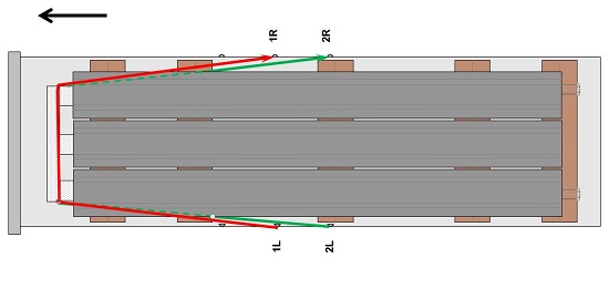
Figure 6 [GDV]
Finally, a few words about end walls and the securing forces they provide.
In vehicles constructed according to EN 12642, the strength of the end wall is described with reference to the payload of the vehicle concerned.
The strength is specified as 40% of the payload up to a maximum of 5000 daN.
If the vehicle is constructed according to EN 12642 Code XL, the strength is specified as 50% of the payload (without any limit).
It is important to note that this strength can only be guaranteed if the cargo is loaded as a tight fit against the end wall, the pressure is distributed evenly over the end wall and the end wall is not damaged.
If this is not the case, and no other adequate securing measures have been taken, the cargo slips, builds up kinetic energy relative to the vehicle and breaks through the end wall, as demonstrated by this Photo of the Month.
At higher speeds, however, the energy that is built up is even higher, with the result that it is perfectly possible for the driver’s cab to be completely destroyed. We do not wish to expand on the consequences here …
Your load-securing columnists wish you a safe and sound journey!
Back to beginning