
| Photo of the month – April 2013 |
[German version] |
Earthquake
The residents of this idyllic spot must have thought that they were experiencing an earthquake or a meteor strike when the walls of their houses trembled one pleasant summer afternoon. The two heavy thuds as the concrete girders hit the ground in quick succession must have been clearly audible, punctuated by the far quieter sound of the two girders colliding (Figure 1). Of course, these noises and tremors did not portend a natural disaster, but were the result of inadequate load securing.
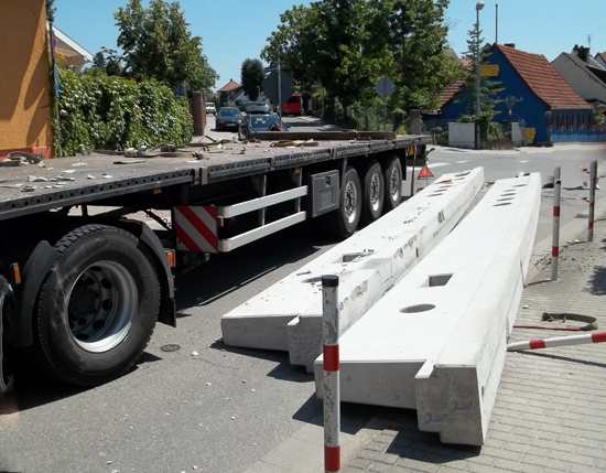
Figure 1 [Stefan Soucek]
This month, our Photo of the Month shows a straightforward flatbed trailer loaded with two concrete girders. Each of these girders weighed in at 8.9 t. The bend or turning the driver was negotiating involved a change in direction of 120°. According to the speed monitor, the vehicle turned out of the junction at a speed of 15 kph. In other words, this accident was not the result of speeding or other external influences.
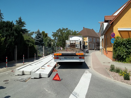
Figure 2 [Stefan Soucek]
We assume that the two trapezoidal girders were standing on the vehicle on their wide face.
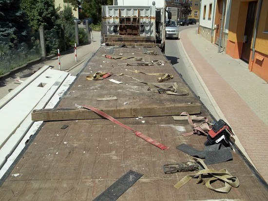
Figure 3 [Stefan Soucek]
But now we see something we did not quite expect: The driver had used a large number of belts. Not only that, they were not just tie-down lashings. The concrete girders were secured by a total of nine round turn lashings. As we can see on Diagrams 2 and 3 below, round turn lashings are passed over and then round the load and tensioned on the opposite side. According to our information, all the tensioners were on the right-hand side. This means that, by chance, the ends of the belts that were subjected to the load happened to be tensioned on the correct side.
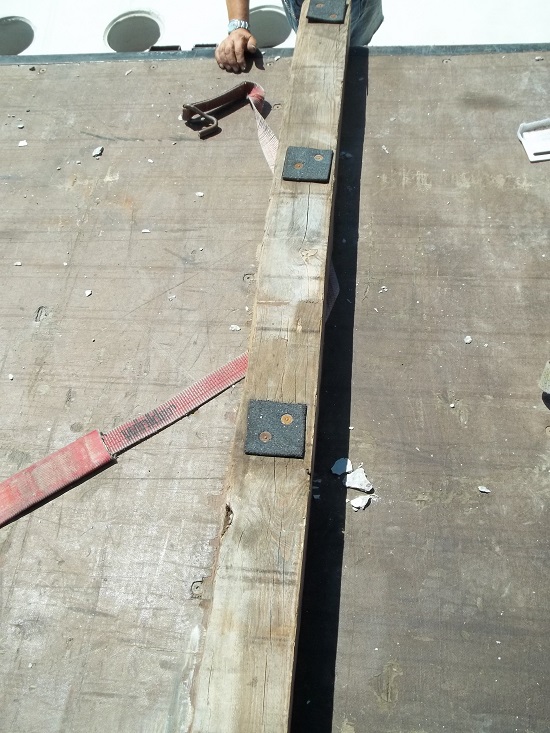
Figure 4 [Stefan Soucek]
And greater care was taken with the dunnage than is usually the case. Although the dunnage unfortunately had a square cross-section, at least it had anti-slip material nailed to it. This had even been done on both sides, i.e. also on the side in contact with the loading surface. At the risk of driving our regular readers to cover their ears and groan, we repeat that dunnage with a square cross-section has a pronounced tendency to roll. This can only be avoided by using dunnage with a rectangular, plank-like format. In this example, there was plenty of dunnage available on the vehicle. If this dunnage had been bolted together in pairs (with the bolted connection being strong enough to withstand the expected loads), the wooden dunnage would have had no chance of rolling. It also makes little sense to simply nail small patches of anti-slip material onto the top surface of the dunnage. Concrete girders would rest on the small surfaces with their considerable weight and additionally balance on the wooden surface to the left or right. If the friction is to be increased effectively, generous amounts of anti-slip material must be glued or nailed to the surface, thus allowing the load to be isolated from the dunnage in terms of friction.
But the thrust of this month’s photo is that the girders were secured using round turn lashings. The diagrams below show two different types of round turn lashings:
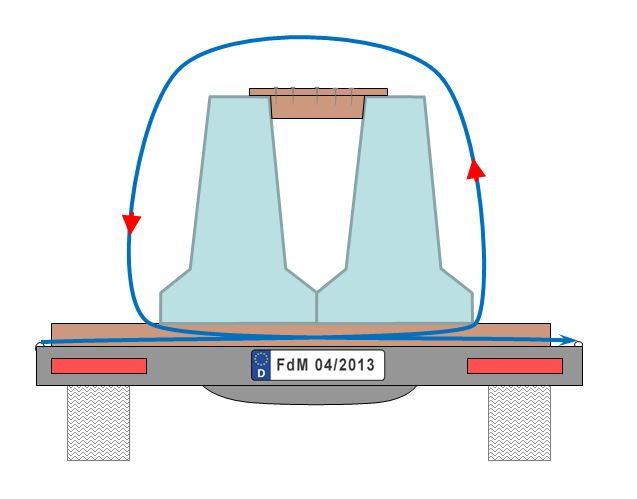
Diagram 1 [GDV]
The round turn from the bottom is the least intelligent variant, as it allows the load to move freely. It only serves to bundle the load and is ineffectual as a tie-down lashing. Furthermore, the friction between the belt and the load is only partially converted to securing force. Unsurprisingly, this type of round turn is often known as a "silly loop". It should never be used!
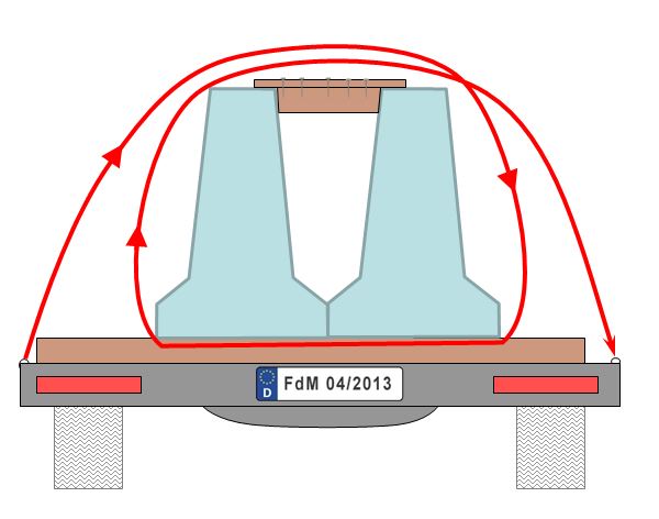
Diagram 2 [GDV]
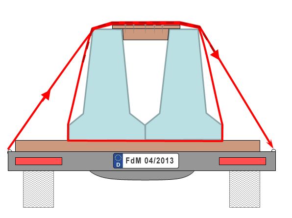
Diagram 3 [GDV]
Diagrams 2 and 3 show the correct way of executing a round turn lashing. It not only serves to bundle the load, but also acts as a tie-down lashing. However, because a great deal of the pre-tensioning force is lost as a result of the high level of friction on the concrete, round turn lashings such as this must be tensioned on both sides. On the other hand, this "lost" pre-tensioning force acts in the same way as a direct lashing, which means that the round turn is a far more efficient securing mechanism than a simple tie-down lashing, but needs two tensioners.
The nub of the problem
It is almost certain that this accident was caused by the fact that the concrete girders were trapezoidal in shape, i.e. they were narrower at the top. As a result of their shape, they were not stable, which meant that the girder on the right was able to tip against its neighbor as the vehicle negotiated the bend. When the girder tipped, the path around the load followed by the belts was immediately shortened with the result that all nine round turn lashings became loose. When the belts were loose, nothing stopped the two girders from tipping still further and ultimately falling into the belts with a considerable amount of kinetic energy, slicing through the belts and finally falling from the vehicle to the left.
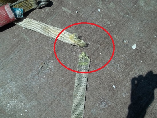
Figure 5 [Stefan Soucek]
Figure 5 shows the ends of two belts that have been sliced through. One of the ends suggests that the belt was torn under great force, and the other suggests that it has been cut. If we look at the relatively sharp, abrasive edges of the concrete girders in Figure 1, it is easy to imagine that they would have no problem cutting through the belts once they started moving.
Improvement
The crucial error that was made when loading these girders was that they were able to tip towards each other at the top. This must be prevented. As we have so often done in the past in this column, we once again recommend the use of spacers. At least two or preferably three lengths of squared lumber are cut to the same length as the gap between the two concrete girders. Boards are then nailed to the top of these spacers. These must be long enough to give the spacers a firm purchase on the girders, but must not protrude beyond the outer edge of the girder. In order to secure the load, loop lashings are then used in preference to round turn lashings. Assuming that the two girders are resting on rectangular dunnage that has been provided with sufficient anti-slip material (preferably vulcanized), four loop lashings – two on each side – are sufficient to secure these girders to the sides. The lashings are passed around the girders, and each end is attached to a separate load-securing point. Chains or wire rope can, of course, be used for loop lashings like this. If belts are used, however, they must always be protected by edge protection sleeves, preferably over the entire distance where they come into contact with the concrete. Because a direct lashing only delivers its full securing force when the load moves slightly in the direction of loading, protection of the load-securing equipment against the sharp, abrasive edges of the concrete is an integral aspect of this method of securing, and not simply a cost-saving exercise on the part of a parsimonious carrier.
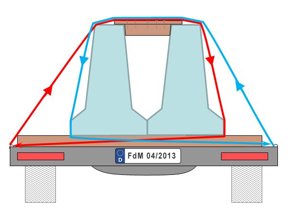
Diagram 4 [GDV]
Diagram 4 shows a traditional loop lashing. This provides all the benefits of direct lashing. It bundles the load and, to a certain extent, acts as a tie-down lashing, damping vibration and oscillation so that friction is always able to take effect. The high lashing capacity (LC) of the load-securing equipment provides a total of 2x the lashing capacity (minus the effect of the angles at cos alpha ½) as securing force (provided that the load-securing points have the same lashing capacity). The disadvantage of this type of securing is that the load must be secured in every direction in which forces act on it.
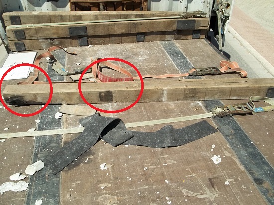
Figure 6 [Stefan Soucek]
During the course of this accident, the concrete girders will also have moved forward slightly. The squared lumber that can be seen in Figure 6 gives some weight to this assumption. This shows that the patches of anti-slip material have become detached. One of these patches can still be seen on the loading surface. This indicates that the squared lumber has slipped or rolled. We would especially draw your attention to the fact that the left end of the squared lumber has already suffered considerable damage. If this side is in contact with the loading surface (this is likely, because anti-slip material was glued to this side), this dunnage is even more likely to roll, because the contact area has been further reduced by the damage.
Securing the load in the direction of travel
Up to now, no consideration whatsoever has been given to securing the load in the direction of travel. In fact, no securing was provided at all. Given a total load weight of just under 18 t and assuming that anti-slip material with a coefficient of friction of 0.6 is correctly used, just 3600 daN securing force still needs to be provided. The shape of the load is ideal for placing a loop lashing round the end of the load. The belts can be placed at extremely favorable shallow angles close to the loading surface, with the result that the angles do not have to be taken into account when calculating the load securing forces. Because the load-securing points, which provide 2000 daN of securing force, are the weakest link in the chain, this single loop lashing round the end of the load is able to provide a securing force of 4000 daN. This lashing is more than sufficient to provide the remaining securing force required. Here also, protective sleeves for the belts are absolutely crucial. Once again, the load must move slightly before the belt is able to deliver its full load-securing capacity. The protective sleeves are vital to ensure that the sharp edges of the concrete do not cut the belts during this movement.
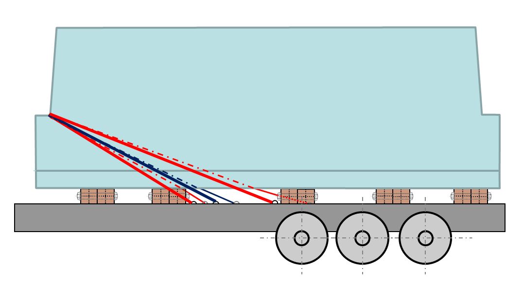
Diagram 5 [GDV]
Diagram 5 also shows a traditional loop lashing, but this time it is employed against the direction of travel. A single belt would be sufficient for our example, but several belts would make eminent sense. If several belts are used to secure a load directly in the same direction, you should make sure that all the belts are of the same length. Direct lashings only take effect after the load has moved slightly in the direction in which it is being secured. In this process, the belt stretches and absorbs an increasing force.
If the belts are of different lengths, the shortest will first be subjected to a load up to its lashing capacity and the longer belts may only take up 60% and 40% of the load. In this example, this effect can be compensated for by placing belt 1 between points 3R and 1R, belt 2 between points 1L and 3R and belts 3 between the load securing points 2L and 2R (see Diagram 6).
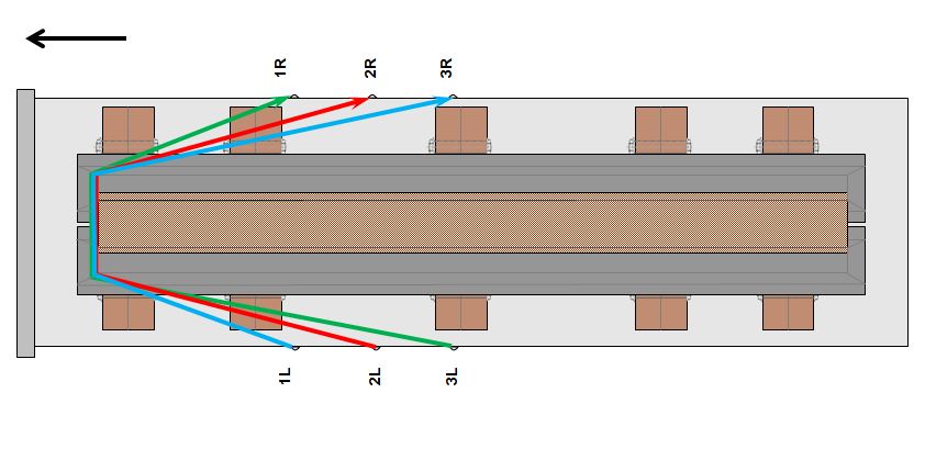
Diagram 6 [GDV]
If, for any reason, it is not possible to place the belts in an offset manner like this, the short belt should be calculated at the value of 100%, the next one with a value of just 60%, for instance, and the third one with a value as low as 40%. The precise values will depend on the lengths of the belts.
Your Load Securing Team
Back to beginning