
| Photo of the month – March 2013 |
[German version] |
Perfection is in the pipeline
This time, our Photo of the Month shows an almost exemplary case of load securing. The pipes and the cylinder on the trailer that looks rather like a tank are made of plastic and are light and cylindrical, which means that they would part company with the vehicle when subjected to any acceleration force if they were not secured. Quite clearly, those who were responsible for this transport gave it a considerable amount of thought and the load securing measures they adopted are almost exemplary.
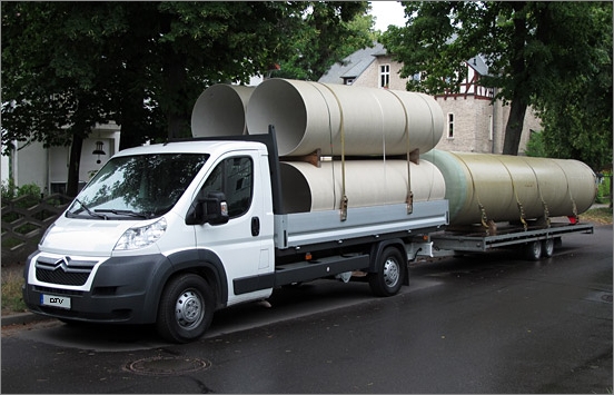
Figure 1 [GDV]
As can be clearly seen on the left of the vehicle, a total of six tie-down lashings with long-lever ratchet tensioners were used. Provided that a modicum of pre-tensioning force was applied to the load with these ratchet tensioners, we can assume that the load is in principle well secured.
If we have a closer look at the load, we can see a belt on the rear of the cylinder on the trailer that has nothing to do with securing the load, but rather appears to be some form of packaging:
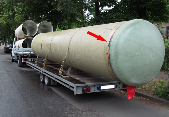
Figure 2 [GDV]
Ignoring the fact that the hooks have been connected in such a way (see arrow) that they would be able to prize each other open, an experienced load securing columnist has to ask why on earth this belt is there at all. Is it possible that the "cap" of the tank might fall out backwards? And is the packaging belt intended to prevent this?
If this is the case, the better solution would be a direct lashing using a head loop. But it is also possible that this belt has merely been used to secure the red flag used to indicate the overhanging load. In this case, we shall not investigate the whys and wherefores of this belt any further.
On both the truck and trailer, the load itself is resting on squared lumber which, at least in part, has a slightly rectangular format:
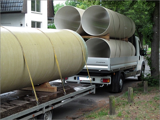
Figure 3 [GDV]
Anyone who reads this column regularly will know of our concern that lumber with a square cross-section has a tendency to roll when a load is applied to it. And so we shall once again point out that even slightly rectangular dunnage is significantly better than square dunnage, but planks or traditional rectangular formats (with a ratio of 1:2 for the sides) counteract any tendency to roll even better.
The biggest problem with cylindrical loads is that they must be prevented from rolling perpendicular to their axis. The most commonly employed method of doing so is to use pipe wedges. In this Photo of the Month, we can see two types of pipe wedges. On the trailer, the pipe wedges were nailed to pieces of squared lumber and on the truck itself, we can see dual pipe wedges on the second layer. These dual wedges are also nailed to pieces of squared lumber to form a clamp.
To start with, let us have a look at the pipe wedges on the trailer.
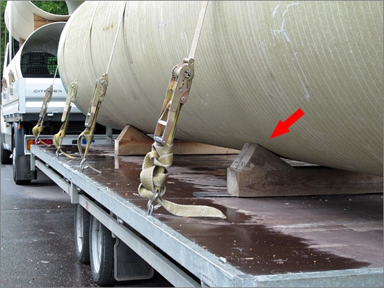
Figure 4 [GDV]
There are a number of recommendations relating to wedges and pipe wedges. The VDI Guideline 2700 for pipe wedges used to prevent loads from rolling sideways states that they should be dimensioned in such a way that there is an angle of at least 35° between the perpendicular through the center of gravity of the cylindrical load and the surface on which the load rests on the pipe wedge.
Furthermore, care should be taken to ensure that the cylinder rests on the wedges in such a way that it is not supported in the middle. This maximizes the lateral securing effect of the wedges.
If this relationship between the wedge and the cylinder cannot be achieved, for instance with large cylindrical bodies, additional load securing measures can eliminate this "shortcoming".
Size of the wedges:
There is a rule of thumb for selecting the correct size for wedges used to secure loads on the roads: According to this rule of thumb, the wedges should have a height approximately one tenth of the height of the cylindrical body (diameter).
Position:
The wedges should be positioned on the bearing surface in such a way that the point at which the load makes contact with the wedge is approximately half way along the flank of the wedge. In Figure 4, you can see that the point of contact with the cylinder is well into the top third of the wedge. In the case of heavy loads, there is then a risk that the force exerted by the weight of the load can wrench the wedge from its anchorage. With an extremely light load such as this one, however, there is no such risk.
Pipe wedges
Wedges must always be cut and used in such a way that nails can be driven into the side along which the grain runs. The load itself, on the other hand, should, wherever possible, rest against the end grain of the wood, because this is far more capable of withstanding loads than the grain side. With a light load such as this one, this does not present a problem, but is of significance with heavier loads.
Driving nails into the end grain is a far greater problem. If you wish to chop wood, you always drive an ax or chopper into the end grain.
The results can end up very similar if you attempt to drive nails into the end grain. Furthermore, wherever possible the nails should be driven vertically through the wedge in such a way that the nail passes approximately 5 cm through the wedge and 4 cm into the supporting lumber. The nails should also be staggered to minimize the risk of splitting the wood. The nails in Figure 5 are close together and would thus exacerbate any tendency for the wood to split under load. In addition, they have been driven in along the grain, which reduces the extraction resistance of the nails to a minimum:
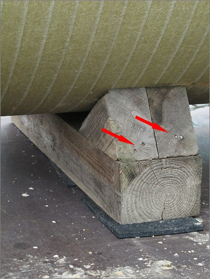
Figure 5 [GDV]
Friction-enhancing material
Figure 6 is a prime example of the inconsistent use of friction-enhancing materials.
In some places, friction-enhancing material has been used on this vehicle. This was placed beneath the dunnage and, as shown in Figure 6, between the load and the dunnage as well. Unfortunately, this was not done systematically:
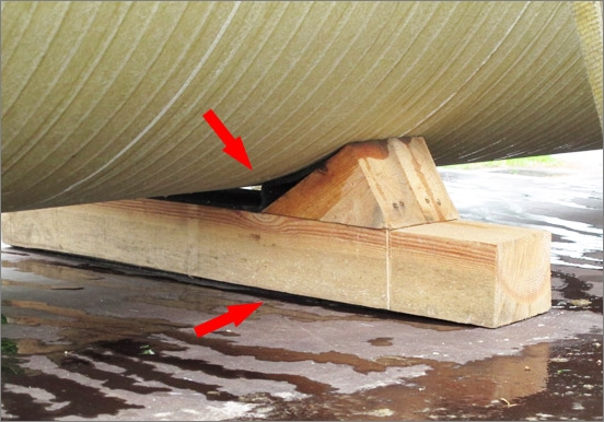
Figure 6 [GDV]
Friction-enhancing material must always isolate the load from the loading surface or the supporting surface in terms of friction. In other words, the only points of contact must be between the friction pairs load/friction-enhancing material, friction-enhancing materials/dunnage and dunnage/friction-enhancing material/loading surface. The excellent friction qualities of the friction-enhancing material only work to best effect if this is the case.
Figure 6 shows that when the plastic pipe was loaded, the anti-slip mat was pushed down and that the pipe is primarily or even completely resting on the wedge with no friction-enhancing material between them (see top arrow). In addition, friction-enhancing material is only present under the middle of the dunnage (see bottom arrow). The outer edge of the squared lumber is in contact with the loading surface, which must be avoided at all costs. It is not necessary to place friction-enhancing materials under the entire surface, but the friction-enhancing material used must be thick enough to ensure that the dunnage is raised sufficiently to prevent any contact with the loading surface even after the cargo has been loaded.
If cylindrical loads are stacked, this can be done using pipe clamps or dual wedges. When fabricating the dual wedges, extreme care must be taken to shape them in such a way that they allow the pipes to be stacked exactly vertically.
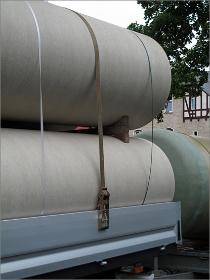
Figure 7 [GDV]
Figure 8 once again shows pipe wedges that have been cut incorrectly. A cutting pattern for pipe wedges and crate wedges can be found in the Container Handbook (Section 4.3.8 "Securing by nailing"). In Figure 8, we can once again see that nails have been driven along the grain of the pipe wedges:
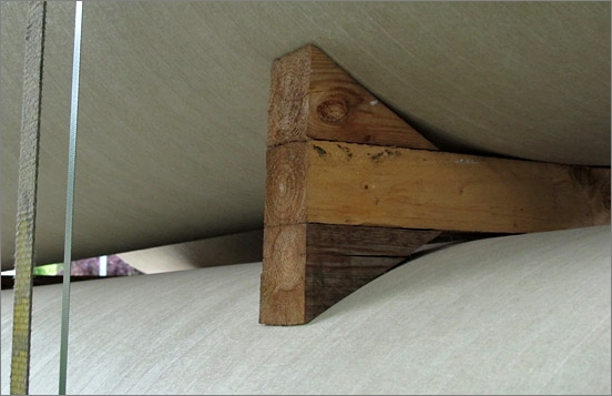
Figure 8 [GDV]
We found our final blemish in this exemplary load in the form of a belt that is pretty well fit for scrapping:
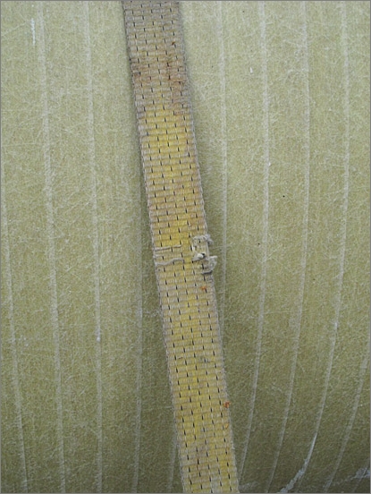
Figure 9 [GDV]
To avoid any misunderstanding:
In this column, we sometimes give the impression that we are nitpickers who find it difficult to admit that any load should be declared "good". Far from it. We just want to eliminate those small errors that can have serious consequences.
In the case of this exemplary load, friction-enhancing materials were unfortunately not used systematically. The result of this can be that the positive influence of the friction-enhancing material does not take effect or does so only partially. This is a waste of valuable working time and material. If wedges are cut incorrectly, they can also be rendered completely useless. It does not cost a penny more to cut wedges correctly, and the cutting pattern is available on the Internet free of charge. They just have to be used correctly. Any carpenter knows that nails should always be driven into the grain side of wood and not into the end grain. It would appear that this intuitive knowledge about the behavior of wood is lost when we hit the road.
Finally, a word about twisted belts. In Figure 3, we can see that a belt has been twisted when it was attached. Unfortunately, this is often noted when vehicles are inspected and is criticized by those who offer training courses in load securing. This is because forces are no longer transmitted optimally if the belt is twisted over the load. And this really should be avoided.
If, however, belts are twisted by a half turn only in order to prevent them from vibrating in the wind and possibly make an uncomfortable chattering noise, this is (generally) of no significance with respect to the securing force. In fact, it is more problematic if the belts vibrate in the airstream and work into the edge of the load, whatever its nature. Even with the best edge protectors, this does the belt no good. Belts are light, easily handled and are able to generate considerable securing force. But precisely because they have these characteristics, they flap in the wind, and steps can be taken to counteract this with a clear conscience.
We wish you and your load a safe and secure journey.
Your Load Securing Team
Back to beginning