
| Photo of the month – January 2011 |
[German version] |
Torpedoes
To start with, may we wish all our readers a healthy, happy, successful and above all secure 2011! We hope that our photos of the month not only entertain you, but also give you pause for thought, and perhaps even encourage you to take the initiative and raise awareness among your colleagues, friends, acquaintances and even your competitors.
We sometimes ask ourselves whether the style we have adopted in our column is the best way of approaching the issue. But ultimately, we rely on our instincts – our gut feelings. We spice up our explanations of why an attempt to secure a load is in our opinion less than ideal with a little sarcasm, just to emphasize the point. But we really don’t want to upset the driver involved – after all, everyone started out knowing nothing about securing loads at some time in their career.
The lengths of our descriptions of how to improve the way a load is secured often vary significantly. Here again, we rely on our instincts. Whenever we feel that there is a need for detailed explanations, we explain a little more, otherwise we explain a little less.
To ensure that we can carry on presenting interesting photos for you this year as well, we would like to ask you to send us any photos that you think may be relevant for publication as a photo of the month. The important thing is that you own the rights on the photo and can transfer them to us in the event of publication.
But now to the case in hand:
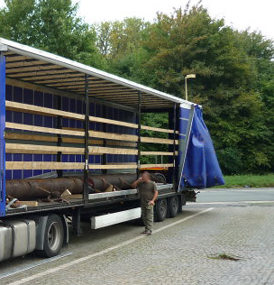
Figure 1 [Peter Proca]
Figure 1 shows a curtainsider loaded with round steel bars. Even the first impression suggests that the load must be both round and extremely heavy, because we must assume that a vehicle carrying steel is loaded to capacity, and this load has a very low center of gravity. Because the load is round steel, readers will already have become very alert to the load securing measures that are necessary. The photo also shows load securing equipment that initially appears to be tie-down lashings. They could, however, also be loop lashings, as this method of securing would be appropriate to counteract the rolling tendency of the round load.
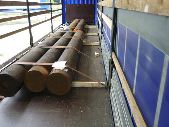
Figure 2 [Peter Proca]
If we have a closer look at the load, our suspicion that it is very heavy is confirmed, as we can see that it is made up of solid steel bars. If we assume that the vehicle is loaded to capacity, each steel bar weighs around 5 tonnes. Load distribution considerations were taken into account during loading. Only two steel bars (i.e. 10 tonnes) have been loaded at the front and at least 15 tonnes have been loaded at the back. The load is resting on square 8 x 8 cm or 10 x 10 cm dunnage and is indeed secured with a special form of tie-down lashing.
At sea, this securing method is known as a round turn lashing. "Round turn" means that the belt passes around the load once and is then tensioned on the opposite side. The securing method is intended to hold the load together, i.e. to prevent it from rolling to the left or right, while at the same time lashing it down.
Effectiveness of the load securing measures
In fact, the load securing measures, comprising just the belts, only have the effect of tie-down lashings. The rear load block, comprising three round bars with a weight of around 15 tonnes, is secured by four tie-down lashings at angles which are probably less than 45°.
Direct measures to increase friction have not been taken, unless one chooses to regard the lumber beneath the load as such. In principle, it is true that fresh-sawn softwood can be used to improve friction. However, because square lumber has been chosen here, the effect when forces act upon the load will merely be to promote the tendency of the load to roll forwards, and it will in no way enhance friction. As far as we see it, the use of the square lumber is particularly serious, because it concentrates the entire weight of 15 tonnes on two strips that nowhere near cover the entire width of the vehicle, as we shall see later. Instead, they concentrate the entire force exerted by the load in the middle of the vehicle.
But back to our round turn lashings. We now want to examine their effectiveness as tie-down lashings and methods of bundling the load.
Bundling
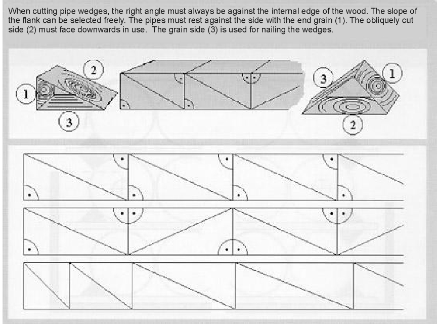
The round turn lashing encloses each of the outer round bars around 50 % of their circumference. This means that the friction of the load securing equipment over 360° (distributed over four round turns) prevents the load from rolling sideways. No further securing to the side could be seen. The wedges apparently only played a role while the vehicle was being loaded and the load was being secured, since they are not attached to the squared lumber placed under the load by nails or screws or in any other way. As can be seen from Figure 3, the wedges have also been cut incorrectly. If a wedge is to be used as a pipe wedge, it must be possible to drive nails into the grain side of the wood and not into the side cut across the grain as indicated by this Figure. Every nail driven into the grain of the wood promotes splitting of the wedge and cannot be used for securing purposes.
The efficiency of the tie-down lashing
No less than seven tie-down lashings with angles of 30° have been used for a total load weight of 25 tonnes. We are aware that the angles are slightly larger than 30°, but prefer to use 30° as the angle for rough calculation purposes, because at this assumed angle we simply have to halve the load securing force (securing force x 0.5).
If we assume that only long-lever ratchet tensioners were used with this tie-down lashing and we ignore the fact that the lumber placed under the load promotes its tendency to roll rather than enhances friction, and instead use the good friction characteristics of the freshly sawn lumber, we could start our calculation as follows: Pre-tensioning force per belt from the long-lever ratchet tensioners = 500 daN. Although the round turn means that nothing of the pre-tensioning force reaches the other side, we still assume 100 % pre-tensioning force on both sides, because the driver will in all probability have managed to roll the round bars to the left side when applying the pre-tensioning force. This rolling effect will have distributed the pre-tensioning force optimally over both sides. We can therefore assume that a total pre-tensioning force of 7,000 daN was applied to the 25 tonnes. The coefficient of friction on the freshly sawn lumber is assumed to be 0.4. The reduction in efficiency caused by the angle is assumed to be 0.5. This results in the following calculation: 7,000 times 0.4 results in 2,800 daN securing force, times 0.5 for the angle of the belts leaves a securing force of just 1,400 daN.
If we actually assume a coefficient of friction of 0.4 for freshly sawn lumber (which is certainly a very generous assumption, as any safety-conscious load securing expert would have assumed a maximum of µ = 0.3), 10,000 daN of load securing force in the direction of travel still have to be found. At least the seven tie-down lashings provide 1,400 daN. If we continue to assume a coefficient of friction of 0.4 when assessing the load securing force to the rear, we still need an additional 2,500 daN. Even here, the 1,400 daN of securing force delivered by the tie-down lashings is insufficient.
Regular readers of the column will undoubtedly already have asked themselves "and what about the middle round bar? Surely this is only secured indirectly by the tie-down lashings, if at all."
It is indeed difficult to establish the securing force applied to a round bar in the middle by a round turn lashing. The tie-down effect of the belts does not secure it at all, as it doesn’t even reach it. Nevertheless, the round bars are pushed together by the pre-tensioning force of the belts, which also "secures" the middle round bar. We shall leave it open whether the middle bar is actually secured and how effective such securing might be. For now, it is sufficient to observe that the tie-down lashing was insufficient even for securing to the rear.
Securing to the side
As we have already mentioned, the round turn lashing achieves its securing force exclusively by the friction of the belts on the round bars. Because we use the friction is securing equipment against the load itself when considering the load securing measures, we can effectively ignore this friction and look for other securing measures. Because, as we have already mentioned, the wedges are not firmly attached, have been cut incorrectly and have not been nailed or screwed in any way, any securing effect they provide will also be negligible. As a result, securing to the side appears to be a problem of at least the same magnitude as securing in the direction of travel, because friction against the underlying surface is also negligible, as this is only made up of rolling friction.
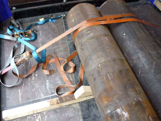
Figure 3 [Peter Proca]
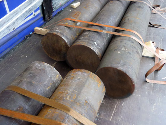
Figure 4 [Peter Proca]
Figure 4 once again clearly shows the path of the belt in the round turn. It also suggests the fact that the wedge is cut incorrectly.
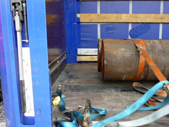
Figure 5 [Peter Proca]
Figure 4 has already shown us that the loader has paid no attention whatsoever to loading the bars as a tight fit. Neither the rear load block nor the front load block forms a tight fit either with the other load block or with the end wall. If you take our rough calculation of the required load securing forces, there is a shortfall of 8,600 daN to the front. This securing force could not be provided by a "normal end wall". If the end wall were to be used for load securing purposes, extensive load distribution measures would need to be taken, because the two round bars have all the charm of a torpedo at a distance of 30 to 40 cm from the end wall. This component of the vehicle can only withstand forces without being destroyed if they are distributed evenly.
Condition of the load securing equipment
It is not only Figure 5 that shows the frightful condition of some of the load securing equipment, although this is where it is seen most clearly. It would seem that the quality of the load securing equipment matches the quality of the chosen load securing method.
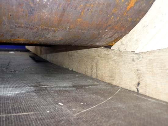
Figure 6 [Peter Proca]
In Figure 6 you can see that the squared lumber has been bent upwards by the weight of the round bars. The entire load is probably concentrated on one third of the length of the lumber supporting it. It is to be feared that this concentrated load has overloaded the deck of the vehicle, although it is not possible to say with any certainty. If you look under the round bars, a fragment of anti-slip mat can be seen. This load securing columnist is unaware of whether this mat was simply there by accident because it had been forgotten, or whether a desperate attempt had been made to favorably influence the friction in some way.
Suggestion for improvement
As far as load distribution is concerned, the round bars are probably arranged correctly on the vehicle. If the lumber placed under the load concentrates the forces excessively on a single point, additional dunnage should be used, where possible in the form of rectangular boards. A rectangular format prevents the lumber from rolling.
Friction
If anti-slip mats are to be used, they must be placed under the entire surface of the dunnage. Fully vulcanized heavy-duty mats should be used on top of the dunnage, since the force exerted by the round bars would in all probability be far too high for granulate mats.
Wedges
If wedges are used, they should be proper pipe wedges secured to the dunnage correctly with one tension mail and two securing nails.
Loads with a tendency to roll can be secured excellently using the loop lashings. Despite the use of wedges, a loader concerned with safety would ensure that the load was secured to the side 100 % by means of belts. This would be achieved by 2 x 4 loop lashings, one to the left side and one to the right side in each pair.
Securing in the direction of travel
And direct lashings or loop lashings around the end of the load (sometimes known as head loops) also make sense for securing the load in the direction of travel In order to be on the safe side (which makes sense for such heavy loads), the anti-slip mats are only assumed to have a coefficient of friction µ = 0.4. The front load unit weighs 10 tonnes and, taking into account the coefficient of friction µ = 0.4, has to be secured with the securing force of 4,000 daN. In theory, this 4,000 daN could be achieved with a single belt used as a loop lashing. Because the lashing angles that arise also impact on the performance of a direct lashing, at least two lashings should be used to the front. Lumber or similar should be placed under the belts in order to prevent them from slipping off the load. Of course, this lumber must also be properly secured to ensure that it cannot shift under any circumstances. It is not necessary to secure the front load unit to the rear provided that both load blocks are loaded together as a tight fit.
The rear load block can also be secured to the front using the two loop lashings, since in this case also, "only 6,000 daN" still need to be found. Suitable squared lumber must, of course, be used to provide an even front to the load, ensuring that all three round bars can be secured by the lashings.
The load can also be secured to the rear using a loop lashing.
Assessment
If the securing of the load is improved using our proposal, 13 belts would need to be used. That is 6 belts more than originally used, but, together with the anti-slip mats used, raise the standard of the securing to very safe, compared with the original securing, for which an assessment of catastrophically inadequate would have been appropriate.
Back to beginning