
| Photo of the month – October 2010 |
[German version] |
Convoi exceptionnel
A low loader carrying a crane weighing approx. 70 t was rounding a bend on a country road. The site of the accident was at the exit of the bend. It was on this narrow road that the heavy transporter met a truck loaded with straw coming the other way.
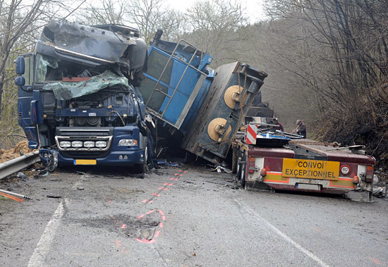
Figure 1 [Raymond Lausberg, Pascal Van Wilder – CEAC S.A.]
We have no statements from the driver himself, so we can only conjecture as to exactly how the accident happened. Either the low loader was traveling too fast at 35 kph for the road conditions at the site of the accident or the driver steered slightly to the right to allow sufficient space for the oncoming truck on the narrow road. Such a maneuver may well have may have been the decisive factor in causing the load, which was clearly inadequately secured, to have slipped.
Just at the moment the two vehicles passed, the crane slipped off the left of the low loader, and hit the road and the oncoming truck. The crane came to rest on the load of straw, which caught fire as a result of the accident.
Since the extreme damage to the oncoming vehicle leads one to fear the worst, let us put your mind at rest: The driver survived the accident without serious injury.
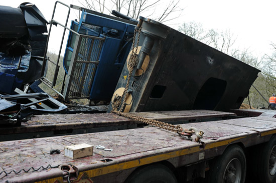
Figure 2 [Raymond Lausberg, Pascal Van Wilder – CEAC S.A.]
Figure 2 presents a chaotic picture that among other things proves that no great attention was paid to securing this load.
The only equipment used to secure the load was chains, which appear to be overdimensioned in view of the load securing points available. The screw pin shackle used seems equally out of place and, in the way it has been used, is unable to align itself freely to the direction of load of the load securing equipment. It is overdimensioned and could therefore not be inserted correctly in the load securing point. The same applies for the load securing chains, on which the hooks were also not suitable for anchoring points such as these.
The fact that some of the chains are still attached to the vehicle and the crane indicates at the very least that the angles used for securing the load to the side were very poorly chosen. According to the reports (unfortunately, there is no picture), at least one load securing point failed.
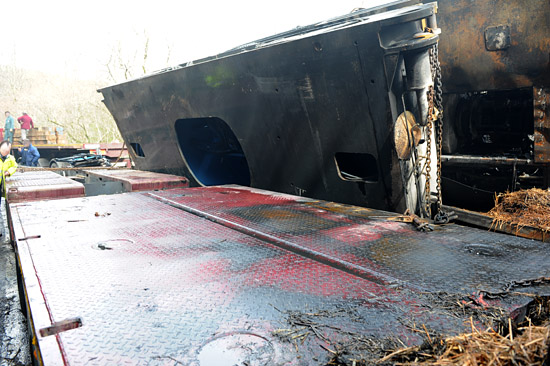
Figure 3 [Raymond Lausberg, Pascal Van Wilder – CEAC S.A.]
On seeing this picture, one has to query the coefficients of friction for this load. To begin to approximate this, it is probable that the completely smooth steel base of the crane was loaded directly on the low loader, which had a steel checker plate loading area.
Figure 4 shows rubber mats that were used with this load:
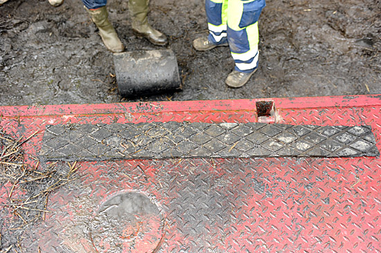
Figure 4 [Raymond Lausberg, Pascal Van Wilder – CEAC S.A.]
The extensive firefighting needed to extinguish the burning load of straw means that it is no longer possible to reconstruct how the rubber mats were placed under the load. The rubber mats do not exhibit the structure that is typical of an anti-slip mat. The right-hand end of the rubber mat shows signs of fraying, which indicates considerable wear.
Only heavy duty mats should be used for loads such as this. When dealing with weights of this magnitude, it is essential that friction is increased. The surface of the vehicle and the base of the crane are crying out for the use of anti-slip mats. If heavy duty mats with a coefficient of friction μ of 0.5 had been used throughout, this accident would probably not have happened.
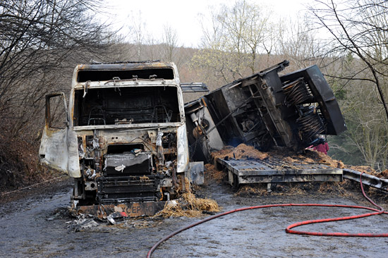
Figure 5 [Raymond Lausberg, Pascal Van Wilder – CEAC S.A.]
Apart from the catastrophic state after the accident and the fire, Figure 5 also reveals that the chains that were attached to the crane from the left to the right of the vehicle are still attached. This is because the load on them was removed when the crane slipped to the left.
Because we have no complete accident report, we can only conjecture that these chains were attached as diagonal lashings, i.e. crosswise. This means that chains must have also been attached from the right of the vehicle to the left side of the crane. These failed during the accident. Among other things, this indicates that the anti-slip materials (rubber mats) were not placed under the entire load. And searching for the rubber mats at the site of the accident also produced only an inadequate amount of anti-slip materials.
However, the claim that they were not placed under the entire load must remain an assumption, as it is possible that they may have been destroyed by the fire.
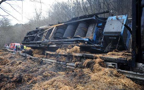
Figure 6 [Raymond Lausberg, Pascal Van Wilder – CEAC S.A.]
Figure 6 shows the site of the accident from the outside of the bend. It clearly shows that the crane fell on the oncoming vehicle.
Despite the clearly visible point of impact in front of the vehicle, the driver survived the accident, which may perhaps be best described as a very lucky escape.
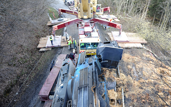
Figure 7 [Raymond Lausberg, Pascal Van Wilder – CEAC S.A.]
Figure 7 shows the site of the accident from above, and indicates the course of the bend. The curve opens slightly in the vicinity of the accident, but its geometry still means that it only permits low speeds. The marks beside the road suggest that the low loader had departed from the carriageway to the right, but this could not be confirmed, and it will not be pursued further.
In closing, just a few comments on how to secure this load correctly. Firstly, we want to underscore yet again the importance of using anti-slip materials, which in this case would absolutely have to be heavy duty mats. Because anti-slip materials alone cannot be used for securing loads, we recommend using a coefficient of friction μ of just 0.4 for approximation purposes when calculating the load securing equipment. (This recommendation cannot be found in any of the guidelines.) That leaves 10 % of the weight of the crane to be secured to the side. If we assume that the existing load securing points have a lashing capacity of 5000 daN, the load can be secured well to the sides using two chains at the front and two at the back. If we look at how to secure the load to the front, we can again use the coefficient of friction μ of 0.5 from the heavy duty mats, because securing to the front is not minimal securing. Instead, 30 % of the weight, corresponding to 21 t still have to be secured. In this case, the load can be secured with appropriate chains, or with other load securing equipment.
Because we have to assume that multiple load securing mechanisms are used, it is vital to ensure that they all have a similar geometry, i.e. that the length and angles are virtually identical. Otherwise, the decrease in strength as a result of the angles or different lengths must be calculated and the load securing equipment must be dimensioned accordingly or additional equipment used. Because the crane has a high center of gravity and, as can be seen in Figure 5, is equipped with good load securing points at the top, it should additionally be secured against tipping at the front and back.
According to our rough calculation, and if appropriate friction-enhancing materials are used, the crane could be secured without any great difficulty using ten to twelve chains – and above all, it would be really secure. The loss of around 2 million euros not only justifies this one load securing exercise, but also correct load securing on all transportation on our roads, after all, let us not forget that the driver barely escaped with his life.
Back to beginning