
| Photo of the month – April 2010 |
[German version] |
A load secured as it should be?
Our regular readers will perhaps raise their eyebrows to see a Photo of the Month with what appears to be praise in the title. Figure 1 shows a thoroughly suitable vehicle and a considerable amount of load securing material. And it is gratifying to see that the facilities provided by the vehicle, namely the stanchions have also been used to secure the load, at least in the direction of travel.
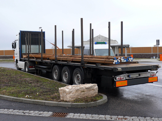
Figure 1
And at first glance, Figure 2 initially touches the heart of the load securing columnist. After all, four stanchions have been inserted in front of the end wall and these have been restrained by a direct lashing, as we have so often recommended in this column, even if the lashing is rather high. The direct lashing with wire rope in combination with a belt provided support for the stanchions that were used to secure the load in the direction of travel.
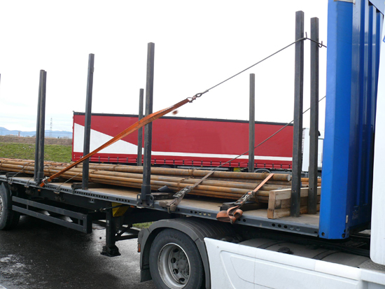
Figure 2
In front of the stanchions, a barrier of squared lumber was built and the load of round steel bars was for the most part loaded as a tight fit against this (Figure 3). If you want to secure loads of this kind in the direction of travel, this can indeed only be achieved by an approach of this kind.
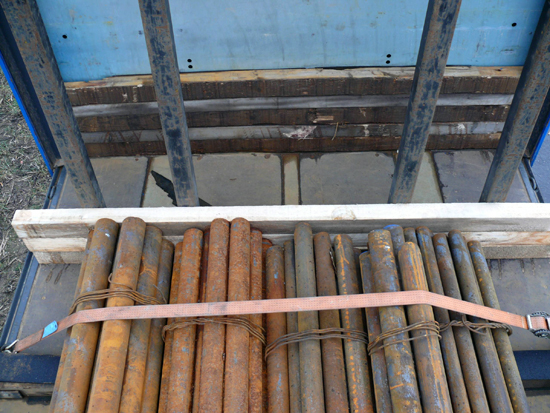
Figure 3
Figure 4 shows the load against the barrier at the front. Sadly, the barrier was not built high enough, so that individual bars would have been able to overcome it without difficulty. A fourth beam would probably have been adequate to increase the height of the barrier sufficiently. Figure 3 above clearly shows additional beams against the end wall that could have been used.
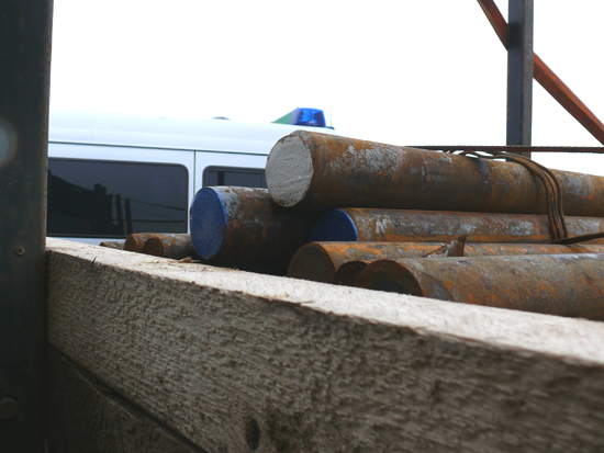
Figure 4
Figure 5 also initially gives grounds for celebration, because the sandwich elements we have so often recommended have been used.
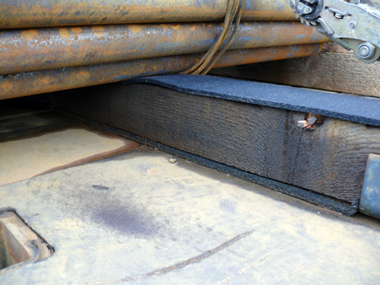
Figure 5
As can be clearly seen in this figure, these sandwich elements are made up of friction enhancing material on the loading area and a squared lumber beam that also has friction-enhancing material on its top side. These sandwich elements "transmit" the good friction values from the loading area directly to the load via the squared lumber. The fact that the squared lumber has a square cross-section is not a problem in this case, because they are screwed to the sides of loading area with steel brackets to prevent them from rolling. This can be clearly seen in Figure 8 below, for instance.
As has already been said, the load was made up of round steel bars that were relatively loosely bundled with wire rope (see Figure 6). The friction offered by the sandwich elements thus works in three ways. On the one hand, in a longitudinal direction to the front and back, but in this case, unfortunately only on the bottom layer of bars. Because the bundles are grouped into a load unit far too loosely with wire rope, they do not form a cargo unit in the direction of travel as far as friction is concerned. To the side, these bundles can, on the other hand, be seen as cargo units.
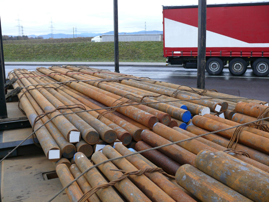
Figure 6
However good the thinking behind the front cargo units may have been in terms of the tight-fit securing used to secure the load in the direction of travel, it was woefully inadequate when it came to the back cargo units. Figure 7 clearly shows that on the left of the vehicle in particular, one bundle is completely unsecured to the front. This means that this load unit would not just slip as far as the bundle in front of it, where its progress would be halted, but would under certain circumstances slip a considerable distance forwards. Figure 3 has already shown how simple it is to build a barrier here and how effective such a barrier is.
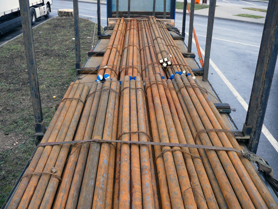
Figure 7
The weight of steel loads means that they are among the most difficult loads to secure. In many cases, they have low friction values, but weigh a very considerable amount. With these slightly rusted round steel bars, the friction would be around 20 to 30 percent. Because no reliable coefficients of sliding friction are available, the lower value should be assumed. It brings benefits to deliberately increase the friction by using friction-enhancing material (see Figure 4) or to secure the load using tight-fit securing elements in such a way that friction is no longer a factor. But it is not a matter for debate that load securing is a job that requires extreme care.
Unfortunately, this case reveals the opposite. Figure 8 shows two careless errors: The lashings on the vehicle were all tie-down lashings. In fact, these lashings were in part wire rope. Wire rope is commonly used as lashing equipment, particularly with steel loads, and in principle there are no objections to its use. This vehicle even has diverters between the load securing point and the loading area so that the wire ropes are not bent over the sharp edges of the loading area. The front wire rope runs directly past the diverter and the rear wire rope has included the underride guard in the securing and has bent it. This can happen if the rope was hanging loosely and was then tensioned from the other side. A final visual inspection around the whole of the vehicle is vital to check the load-securing measures. Only then can you be sure that everything is really the way you intended.
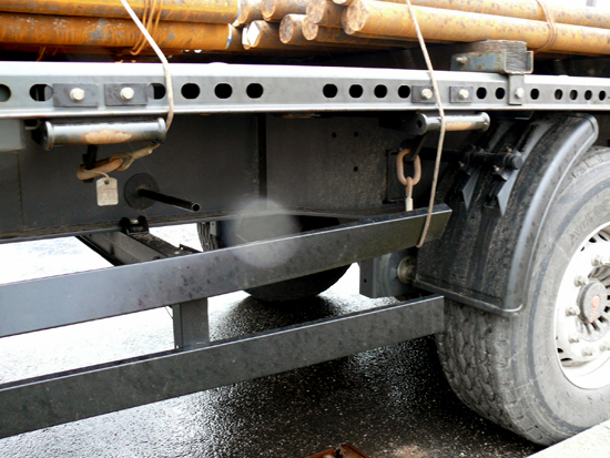
Figure 8
Some fundamental thoughts about this load
The approach to securing the load was excellent. But sadly it was not implemented systematically. But that doesn’t change the fact that knowledge of how to secure a load properly appears to be present and that the loaders are largely aware of the problems associated with securing a load.
The load securing measures taken on this vehicle were all designed as tie-down lashings, which rely solely on friction. Only the outer steel bars were affected by the forces of the tie-down lashings applied by the steel wires and belts that ran at a low height. This means that the effect would have been marginal. With such a low coefficient of friction and such high weights (it is assumed that the complete load weighed some 24 t), tie-down lashings do not make a great deal of sense. A second barrier would have been a sensible measure, and even a third to secure the load to the rear, as this aspect was completely ignored. The directives currently in force stipulate that the load must also be secured to the rear for 0.5 g. Because only the bottom layer was secured with friction-enhancing materials, the top steel bars must be prevented from slipping backwards just as much as the entire load must be prevented from slipping forwards. The barriers also need a tie-down lashing, simply to prevent the barrier from being lost during the journey as a result of vibrations or similar.
How could the loading and securing have been improved?
At the front, the round steel bars are resting against a barrier, which in turn is resting against two pairs of stanchions. These pairs of stanchions are towards the left and right of the vehicle. It would have been perfectly possible to split the load between the left and right of the vehicle and to secure it against the side stanchions with loop lashings. If this were done on both sides, the longitudinal load on the stanchions would have been improved and the side stanchions on the vehicle would have been incorporated in securing the load, which was not the case. A loop lashing effectively prevents the load from rolling or slipping to the side. Friction would have also had a further positive effect.
More of the load was loaded at the rear of the vehicle, probably for reasons of load distribution. But even this load could have been distributed over the left and right sides and could have been excellently secured against the side vehicle stanchions with two belts or wire ropes on each side in the form of loop lashings. The only sensible way of securing the load to the rear is with a barrier, and this would complete securing of the load ideally – provided that no stray parts of the underride guard are trapped.
Back to beginning