
| Photo of the month – December 2009 |
[German version] |
A house of cards
Today we shall look at some concrete slabs that have slipped from the loading bed like a deck of cards that has been nudged. The pictures below vividly illustrate what concrete slabs can do to a car if they are not adequately secured.
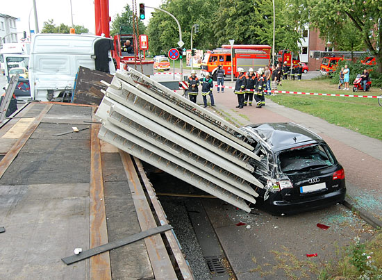
Figure 1 [Guido Mindermann]
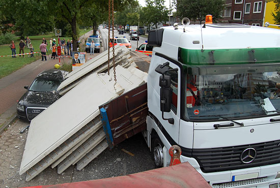
Figure 2 [Guido Mindermann]
The truck had several layers of concrete slabs loaded on a flatbed, secured with tie-down lashings. Judging by the damage shown in the pictures, it is possible that the accident happened as follows: As a result of a braking maneuver in traffic just before an intersection, the concrete slabs slipped to the right off the loading area and damaged a parked car in the process. The car itself was a write-off.
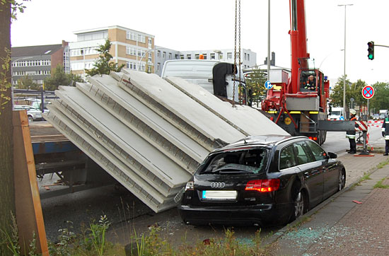
Figure 3 [Guido Mindermann]
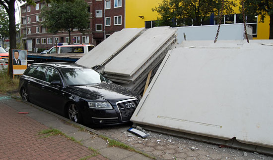
Figure 4 [Guido Mindermann]
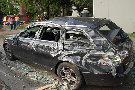
Figure 5 [Guido Mindermann]
The pictures were taken while the scene of the accident was being cleared, so it is only possible to reconstruct the course of the accident to a limited extent.
The two stacks of filigree concrete slabs slipped from the vehicle to the front right as complete stacks. On the one hand, this indicates a braking maneuver, and on the other it suggests either that the driver steered slightly to the left or that the road sloped to the right. The stacks of filigree concrete slabs slipped "en bloc" and fell from the vehicle, which indicates that the friction within the stack was higher than the friction between the stack and the loading area.
The fact that anti-slip material can be seen on the loading area and that its angle shows that it has also slipped a certain distance is a challenge to load-securing afficionados (Figure 1). After all, we are constantly preaching – in this column in particular – that friction is the beginning and end of all load securing considerations.
But friction, and the explicit manipulation of friction is one of those things. Anti-slip materials must be placed under the load in such a way that they are able to completely separate the load from the loading area as far as friction is concerned. And this applies to all conditions that may arise during transport.
Not only that, there must be no dirt (such as concrete dust, sand, gravel, etc.) under the anti-slip materials, as this permanently destroys the good friction values between the load, the anti-slip material and the loading area. Instead, the presence of such materials adds a "new material pair" to part or all of the friction system, and the coefficient of friction of this pairing cannot be determined. Furthermore, the anti-slip material must be thick enough (a thickness of 8 mm is good, and 10 mm is better) to compensate for unevenness in the loading area, even if the loading area distorts. And finally, it must be certain that the shear strength and the specified friction value are also upheld under the given surface pressure.
A suspicion:
If you look at the loading area, you can see the strips of anti-slip matting. They have slipped, but have only slipped part of the distance that the load slipped. Their length suggests that they were only partially under the square pipes, since they are shorter than the width of the vehicle. The metal surfaces can be clearly seen on the loading surface (yellow arrows):
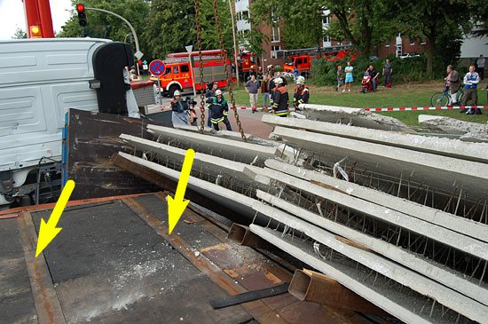
Figure 6 [Guido Mindermann]
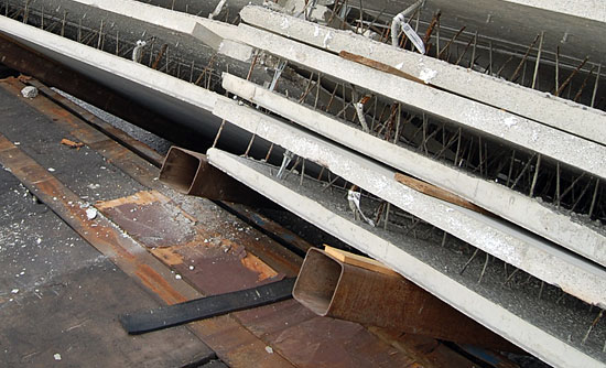
Figure 7 [Guido Mindermann]
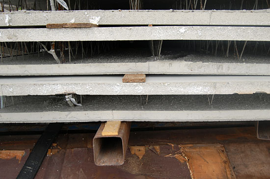
Figure 8 [Guido Mindermann]
The concrete slabs were resting on square cross-section pipes. Square cross-sections have a tendency to roll if loads slip. Wooden boards were placed between the concrete load and the square pipes to increase friction. The fact that these did not roll indicates that the friction between the square pipes and the loading area was far lower than the friction between the pipes and the wooden boards / concrete load. This assumption leads us to conclude that the pipes were for the most part in contact with the metal surfaces of the loading area, thus leading to very low levels of friction. The tie-down lashings slipped with the load to a certain extent before they failed. It is probable that the pre-tensioning force increased considerably as the load slipped and thus helped to stabilize the stacks. The fact that the square pipes did not even roll when the load slipped off the loading area gives a good idea of the importance of friction in the interplay of forces when securing a load.
The end wall was not a great deal of use in absorbing the kinetic energy of the stacks of concrete slabs as they slipped towards it.
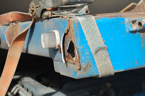
Figure 9 [Guido Mindermann]
Even if freight is loaded in blocks as in this case, a tight-fit method of loading only makes sense if there is an end wall that is capable of withstanding the potential loads. In order to distribute the load efficiently, the sensible approach is to load the freight as a tight fit against central stanchions. The trailer is clearly corroded, but we shall not deal with the issue of whether it was fit for the task in hand here.
The concrete slabs were secured with lashing belts in the form of tie-down lashings. As the pictures below show, the lashing belts were severed or completely frayed by the sharp edges of the concrete slabs. To top it all, they appear to have been used with no edge protectors whatsoever.
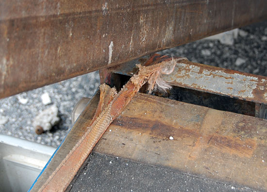
Figure 10 [Guido Mindermann]
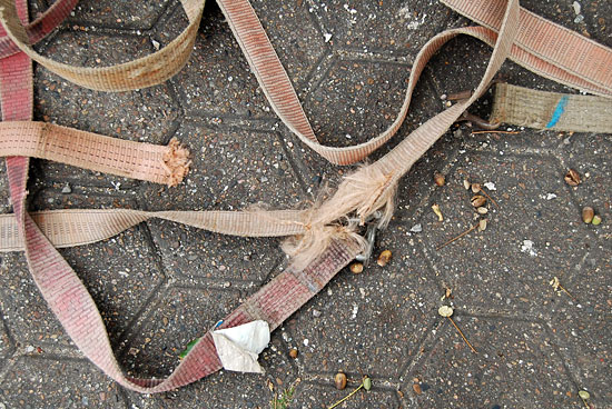
Figure 11 [Guido Mindermann]
Anyone who does not protect their belts against sharp, abrasive edges completely nullifies any efforts made to secure the load. On the one hand, attempts are made to secure the load, but on the other, the sharp edges ensure that the securing materials used will not withstand a great deal when they are subjected to a load. That’s a pity!
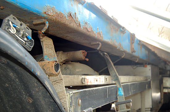
Figure 12 [Guido Mindermann]
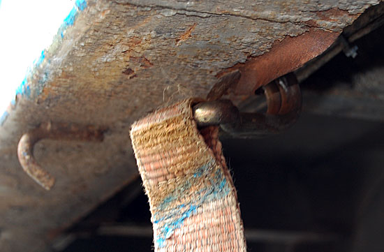
Figure 13 [Guido Mindermann]
What needs to be taken into account with this type of load?
The vehicle and the load securing equipment must be technically sound.
The filigree concrete slabs in the stacks were separated by wooden boards. This pairing of materials has a coefficient of friction µ of 0.4. If greater friction values are to be achieved, it is recommended that sandwich elements are used made from rectangular squared lumber which cannot roll. Like a sandwich, these elements have a layer of anti-slip material attached or glued to each side. Measures such as this allow the coefficient of friction µ to be increased to 0.6.
The load can be secured with tie-down lashings or direct lashings. But a word of caution! This is an overwidth load. This can be clearly seen in Figure 1. The fact that the load is overwidth results in angles on the tie-down lashings that reduce the efficiency of the load securing measures taken. If loop lashings are used, false loop lashings are the inevitable result. This diagram (Figure 13) illustrates the problem. The effectiveness of tie-down lashings is reduced due to the resulting lashing angle (view from the end of the vehicle):
Figure 14
If the lashing angle α = 30° as in the diagram above (Figure 14), the effectiveness of the tie-down lashing is reduced by half!
If loop lashings are used, "false loop lashings" are the inevitable result. "False loop lashings" are loop lashings where the width of the load is greater than the width of the vehicle, with the result that the load is free to move to a certain extent within the loop lashing. The load can thus slip up to the point at which it is restrained as a tight fit again by the load securing material. The following diagram illustrates this:
Figure 15
The diagram (Figure 15) shows that the load is free to move a certain distance within the lashing. This distance is shown as Δ d. Such movement must not be allowed when direct lashings are used, as it allows the load to gather kinetic energy while it is slipping.
The topic of false lashings is dealt with in the GDV Cargo Securing Manual and the chapter on concrete slabs (only available in German).
When loop lashings are used, it is imperative that only true loop lashings are used. The following diagram shows how true loop lashings can be used to secure an overwidth load (view from above).
Figure 16
The following 3D diagram shows the same load securing principle using true loop lashings (the rather unusual geometrical shapes are the result of the graphics tool used for the diagram!).
Figure 17
If true loop lashings are applied as shown in Figures 15 and 16, these are sufficient for minimum load securing to the side, provided that anti-slip material is used between every layer of the load.
Additional loop lashings can be used to secure the load longitudinally (against the direction of travel). This is shown in the following diagram (view from the side).
Figure 18
In our judgement, the best load securing method is to use anti-slip materials throughout, including between the concrete slabs. The load is secured to the front by two stanchions inserted in the center of the loading area, against which it is possible to load the slabs as a tight fit. These stanchions can also be strengthened with belts or chains as necessary (shown in red in this diagram, viewed from above).
Figure 19
In this case, the good friction values (if anti-slip material with a coefficient of friction µ of 0.6 is used) mean that the load only needs securing to the side with a minimum of two, or preferably four, tie-down lashings. In this event, the lashings should be secured in alternating directions.
Back to beginning