
| Photo of the month – July 2009 |
[German version] |
A bombshell in concrete
It is always astonishing to see just how riskily heavy objects are still transported and "secured".
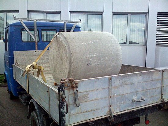
Figure 1 [Marc Wegmüller]
This flatbed truck was used to transport a concrete cylinder. The concrete cylinder in question was open at one end and possessed thick walls. Unfortunately, its precise dimensions are unknown. However, if we assume a diameter in the order of 1 m, a height of 1.5 m and a wall thickness of 10 cm then the weight of the object must have been somewhere between 0.5 and 1 t.
The concrete cylinder was laid on its side across the vehicle in the direction of transport and "secured" against rolling at the front with a single piece of squared lumber (approx. 10 x 10 cm). No squared lumber was placed below the rear of the object. Furthermore, a tie-down lashing was used although the effect of this was purely for show. The lashing belt was passed along the top of the cylinder’s curvature at right angles to the direction of travel. What is more, the fact that it was passed around the sides of the vehicle impaired the load securing angle and made it impossible to calculate the pretensioning force.
It will be clear to anyone that when "secured" in this way, such a concrete cylinder will come loose from the tie-down lashing when the slightest jolts occur during transport – presumably as soon as the vehicle pulls away. What might happen in the case of a slightly heavier braking maneuver does not bear thinking about. (See Photo of the month – November 2006).
How could the object have been correctly secured?
If the concrete cylinder has to be transported lying down then it is advisable to align its axis of rotation with the direction of travel. Only then can tie-down lashings or loop lashings be sensibly applied since the lashing points will then be outside at the longitudinal sides of the loading area.
To ensure correct load distribution, the concrete cylinder should be loaded in accordance with the vehicle’s load distribution plan. It certainly cannot be loaded directly at the end wall with the result that there will be no immediate fit against this wall. The concrete cylinder should be supported by cross-pieces. To prevent the cross-pieces from rolling away in the direction of travel, they should not have a square, but rather a rectangular cross-section. Alternatively, two square cross-pieces should be placed together on either side. Friction-enhancing mats (FE mats) should be placed above and below these cross-pieces, see the diagram in Figure 2.
Figure 2
For reasons of occupational safety, squared lumber should be placed along the long sides of the concrete cylinder during loading in order to prevent it from rolling away after being placed in position. It is not their purpose to provide lateral protection during transport.
To calculate the securing of the load, let us assume a load weight of 1 t.
The load can be secured on each side during transport by means of two loop lashings to the left and right. These must fully protect against lateral forces of up to 0.5 g (i.e. 50% of the weight of the load) since there is no friction in this direction (or only rolling friction). When doing this, different lashing points should be used on either side of the loading area. Due to the adopted viewpoint, only one pair of loop lashings is depicted in the diagram (Figure 3):
Figure 3
Horizontal forces of 0.8 g (80% of the weight of the load) may act forwards in the direction of travel, i.e. in our case a force of 800 daN. The coefficient of friction of the concrete cylinder on a wooden loading area in combination with FE mats can be estimated at 0.6 μ, i.e. 600 daN (in accordance with VDI 2700). 200 daN therefore remains to be secured. This can be achieved by providing bracing from the object to the end wall. This bracing can take the form of wood, e.g. pallets. This wood bears against a cross-piece located at the end wall in order to distribute the forces. This arrangement also provides additional security by means of the tight fit achieved in the forward direction.
Figure 4
| An additional, although more time-consuming, security mechanism would be to install pipe wedges to secure the concrete cylinder at the side. These should be nailed to the cross-pieces. Here again, FE mats should be inserted between the load and the cross-piece or wedges. |  Figure 5 |
 Figure 6 |
These wedges should be cut and positioned in such a way that the nails can be driven into the long side of the wood, i.e. along the grain side, and not into the end grain. 1 and 2: End grain, 3: Grain side |
Alternatively, the concrete cylinder could be transported standing vertically in order to obtain the largest possible contact area and prevent the cylinder from "rolling away". If the load-bearing capacity of the loading area is insufficient, the concrete cylinder should be placed on wooden beams to distribute the load. Here again, it is necessary to place friction-enhancing mats between the load, the wooden elements and the loading area.
Again, it is necessary to remember that 0.8 g (or 80% of the load of the weight) can act as a horizontal force in the direction of transport and that this force must be secured.
As already mentioned, if an FE mat is used then a coefficient of friction of 0.6 μ can be assumed, i.e. a value of 600 daN. This leaves 200 daN to be secured which can be achieved by means of two tie-down lashing belts fixed crosswise. It is essential to protect the lashing belts with belt sheaths or similar. The lashings must not pass outside the sides of the vehicle:
Figure 7
Alternatively, instead of these two tie-down lashings, it would also be possible to use a special safety tarpaulin. Thanks to this, the concrete cylinder can be secured using a mixture of tie-down and direct lashings.
Figure 8
Detailed information on securing concrete pipes on trucks can be found in the GDV Cargo Securing Manual (available in German only) and in particular the section on concrete pipes. The specific dimensions required for wooden pipe wedges are explained in section 3.4 (Wood).
Back to beginning