
|
Photo of the month – January 2009 |
[German version] |
Belts galore
If our normal load-securing afficionados have a look at this picture, they might expect any load-securing columnist to break into spontaneous and prolonged applause at the sheer number of belts used. And it is true that the vehicle and large parts of the entire company are now well stocked with belts. This load of I-beams (we assume that the weight is 24 tonnes, as we were not informed of the exact weight) was "secured" with just six tie-down lashings (the six orange belts in the foreground).
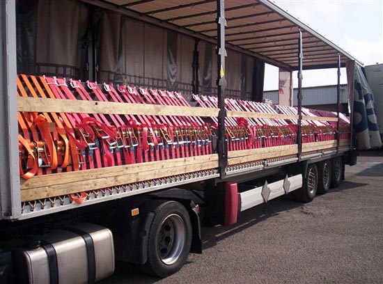
Figure 1 [Klaus Brändle]
During a routine truck check, the officials absolutely correctly determined that the load was thus inadequately secured. Whether it was the officials or the driver who insisted remaining true to the principle of using tie-down lashings was not recorded. But the fact remains that tie-downs were used. However, before this monument to tie-down lashing was realized, a few calculations were done. And these calculations showed that insofar as the load had to be secured using the principle of tie-down lashings, a total of 135 belts would have been needed.
At the latest by the time the results of the calculation were available, all those involved should have drawn the following conclusion:
Tie-down lashings are simply not a suitable method of securing such heavy loads.
As far as this author understands the situation, vehicles such as this are ideal for load securing, but not all load-securing points on the edge profile are permitted to be used for load securing at the same time. Instead, only a certain number per running meter may be used. If all the long-lever ratchet tensioners that appear to have been used here are fully tensioned, they are each capable of generating a pre-tensioning force of 500 daN on the tensioning side. With 96 belts (no more load-securing points were available), this gives a total of 49,000 daN on the tensioning side alone. If we assume a K value of 1.5, pre-tensioning forces of 24,500 daN are still generated on the right-hand side of the vehicle. This means that the vehicle will be subject to a further 73,500 daN in addition to the load weight. Assuming that we are actually dealing with just 24,000 daN load weight force, the delicate trailer is currently being subjected to 97,500 daN at this moment. One is entitled to ask whether it is able to withstand that!
And that’s not all: It is not just the loading area in the middle that is being subjected to forces. The outer edges of the vehicle frame are being pulled strongly upwards with the result that the loading area of the trailer probably resembles a bathtub rather than a truly flat surface.
Because they are all neatly aligned, it is particularly clear to see that all the tensioners were attached on the left of the vehicle. This means that the pre-tensioning forces are distributed extremely unevenly and if subjected to a load would undoubtedly tend to slip to the right to get up to mischief there (as we clearly saw in the Photo of the Month from November 2008).
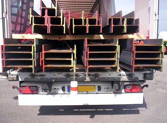
Figure 2 [Klaus Brändle]
Seen from the rear, the entire monument to load securing becomes completely absurd. The I-beams have been stacked in packages, but not bundled, and between the individual packages, gaps in the load can be clearly seen. Tie-down lashings, however, always generate diagonal, inward-pointing forces that act on the top, outer edges of the load. As soon as this vehicle starts moving, the considerable pre-tensioning forces of no less that 73,500 daN will ensure that the load will close up. But because, as we have said, the pre-tensioning forces are not distributed homogeneously, the load would slip to the right.
If you look at the squared lumber dunnage that can be seen from the back, you get an impression of the extent to which it is suffering under the almost unbelievable pre-tensioning forces. Even with the vehicle at a standstill, the weight of the load and the massive pre-tensioning forces have caused the steel to cut into the wood. How long the dunnage above the second stack of I-beams from the left on the loading area can continue to hold out must surely only be a question of time.
So how can a load such as this be loaded sensibly, economically, quickly and effectively?
| To start with, all wooden interlayer dunnage must be suitably strong and should have board format, because, as we have so often pointed out, square cross-sections contribute to the load rolling. | |
| Friction is always a valuable accomplice in securing a load. And so friction-enhancing materials are also the order of the day in this case. They must be placed above and below the wooden dunnage and it is vital to make sure that only heavy-duty FE materials are used that are able to withstand the attendant loads. | |
| If a fork-lift is used for loading, gaps in the load must be avoided at all costs. If a crane is used for loading, thus necessitating gaps between the individual packages in the stacks, it is possible to insert vertical squared lumber dunnage during loading and to load the packages up against this dunnage. This makes it possible to achieve an ideal tight-fit. |
Securing to the side
No matter how hard you try, the bottom four packages will always be wider than the top three. This means that the loop lashing load securing method will have to deal with the individual packages separately. If we assume that the four bottom packages have a total weight of 14 tonnes and that FE materials have been used at least under the I-beams, the bottom packages should be able to be secured well to the side using two loop lashings each. These loop lashings are executed best if the belts are laid out before the second layer of small steel packages is loaded. The lashings can then be tensioned when loading has been completed. The second layer of smaller packages can also be well secured to the side with just four loop lashings.
Observant readers may have noticed that it was only possible to place FE material below the beams and not between the beams themselves, and that the good coefficient of friction can therefore not be used consistently for all the beams. That is correct! And yet the I-beams are stacked and interlocked in such a way that a block is effectively formed. It is only possible for beams to rub against beams in the outer areas. The direct lashing method (to the side), however, prevents this.
Securing in the direction of travel
Because the many belts prevent us from seeing the load clearly, we must assume that the load consists of I-beams that occupy the entire length of the trailer. We were not informed whether the load was loaded as a tight fit against the end wall. Neither do we know what load the end wall is capable of withstanding. To allow a margin for safety, we shall assume that the end wall has a maximum load-securing capacity of 5 tonnes.
Let us first look at the bottom layer of the load with a weight of 14 tonnes. In the direction of travel, we have to take into account that only the bottom layer, i.e. 4 I-beams (approx. 3.5 tonnes) are in contact with the FE material. We assume a coefficient of friction µ of 0.5 for the FE material. This means that a further 1,050 daN still needs to be secured. The 10.5 tonnes on top of this have a maximum coefficient of friction µ of 0.3 on the rusty beams. To allow for a margin of error, we have used a factor µ of just 0.25 in our calculations, because we do not have any reliable friction values. This means that a further 5,775 daN of securing force are still needed for this section. This makes a total of 6,825 daN, which would exceed the capacity of the end wall.
The following solution is possible: The two middle packages could be loaded directly against the end wall as a tight fit using suitable load distribution mechanisms. A gap in the load of approx. 5 cm is left in front of the two outer packages. The form of the I beams means that it is possible to pass loop lashings in the form of head loops around the ends of the outer packages. The method of loading and the shape of the beams mean that these direct lashings can be realized on one side only, i.e. they do not have to be passed diagonally across the entire load stack. This considerably facilitates lashing. To secure the load packages on the second layer, it is either necessary to build a barrier of lumber that is then restrained with loop lashings or a total of six loop lashings are needed to secure the load to the front.
Note
If the I-beams had been nested and loaded on end, each I-beam would have had contact with the FE material and it would have been a far simpler matter to secure the load to the front. Sadly, the material does not always allow nested loading.
Securing to the rear
If all the I-beams were in contact with the FE material, the use of just three to five tie-down lashings would have guaranteed the minimum securing level, and we could say that the load was secured adequately. This author is, however, not happy with merely adequate load securing and would prefer "good" load securing. And therefore we would at this point recommend four loop lashings for the bottom and six as we used above for the top packages. And the same applies again here: I-beams are far easier to secure as a block using belts, chains or wire ropes if they are on end. In this case, the risk of slipping means that each stack of I-beams must be secured more or less individually.
Now some experts would like to point out that at least the bottom packages of I-beams no longer need to be secured with loop lashings because the top packages exert force on the bottom ones and because they are lashed directly, their weight effectively acts as a tie-down lashing. And indeed, they do make the lower layer of the load heavier and it is probable that such experts would be right (it would be necessary to perform the calculations layer by layer through the entire load). But the fact is that the second package from the left would not be affected, and the extremely complex calculation would have saved a mere three loop lashings that could have been put in place in a matter of minutes given the appropriate preparation.
Safety is always worth that little extra!
Back to beginning