
| Photo of the month – December 2008 | [German version] |
On a knife edge!
Our regular readers may well be thinking to themselves "how dull – steel again!." But it is not as if we are running out of pictures or that we can´t think of anything else. It´s simply that steel is one of the most difficult, most complicated loads to handle and gives plenty of scope for identifying errors, special issues, dangers and foolish carelessness. And our Christmas issue is no exception.
About the load:
A total of 21.68 tonnes of I-beams had been loaded on an articulated truck. The stacked steel sections in the middle of the loading area were shorter than those placed on the outside. A considerable gap had been left between them and the end wall of the trailer. The four I-beams loaded on the outside were longer and protruded over the end of the loading area. The total load was "secured" with eight belts used as tie-down lashings.
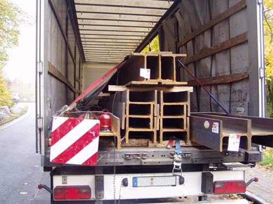
Figure 1 [Frank Horstmann]
When trying to assess the load securing in this case, even a hardened load-securing columnist has difficulty maintaining their composure. The 21.68 tonnes were secured against floating away upwards with eight belts (40,000 daN / minus the amount subtracted for the angles).
Securing 21.68 tonnes of steel in the direction of travel using tie-down lashings and assuming a maximum coefficient of friction µ of 0.2 would require a pretensioning force in the region of 65,000 daN. This means that at a total pretensioning force of 1,000 daN per belt, 65 belts would be needed, and at a total pretensioning force per lashing of 500 daN …
This calculation is only intended to indicate the idiocy of this attempt to secure the load.
But we don´t wish to bore our readers with sarcastic comments about the use of tie-down lashings to secure heavy loads with poor coefficients of friction. No, instead we wish to take you aside and develop a theory.
As is so often the case, all eight tie-down lashings were tensioned on the driver´s side. No friction-enhancing materials were used under the load itself, but it was used in part under the belts. Because the belts had no protective sleeves, friction-enhancing material was used to protect them from the sharp edges of the load.
This means that the friction between the belts and the load was very high and the K value very low. This means that the pretensioning force must have been relatively high on the driver´s side and relatively low on the right-hand side of the vehicle.
The forces exerted by the belts are applied to the top corners of the load. These forces act diagonally through the load down to the bed. These diagonal forces mean that the load is pushed not only onto the loading area, but also to the side. Since the forces on the driver´s side (left) were stronger and there was thus an imbalance, the load would tend to give to the right rather than to the left if it moved.
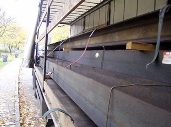
Figure 2 [Frank Horstmann]
And this was the result! Of the eight belts originally used, six were completely severed and two were literally hanging on by a thread. We have the following theory:
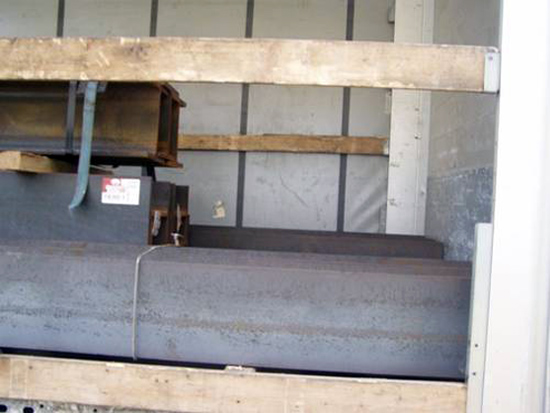
Figure 3 [Frank Horstmann]
Even if this picture suggests that the long I-beams formed a tight fit against the end wall (the 1-meter plus gap between the short I-beams and the end wall can also be clearly seen here), the next picture tells a different story.
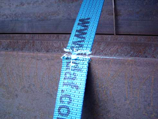
Figure 4 [Frank Horstmann]
The load was placed on the loading area with a gap of around 10 cm to the end wall. An unspectacular braking maneuver caused the load to slip hard up to the end wall. This can be seen clearly on the steel beam, which abraded blue fibers from the belt as it tried to sever it.
Because the load was subject to pressure from the left-hand side, it not only slipped forwards, but also slightly to the right of the vehicle, and in the process severed almost all the belts. On the left-hand side, the belts were doubled, because the ratchet and the hook are sewn in at that point. This meant that the belts survived longer there.
The following pictures show that the driver frequently transports steel and sadly pays insufficient attention to protecting his belts. The state of the belts is simply appalling and they are only fit to be scrapped.
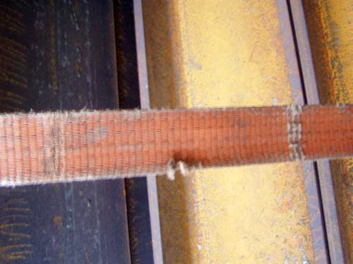
Figure 5 [Frank Horstmann]
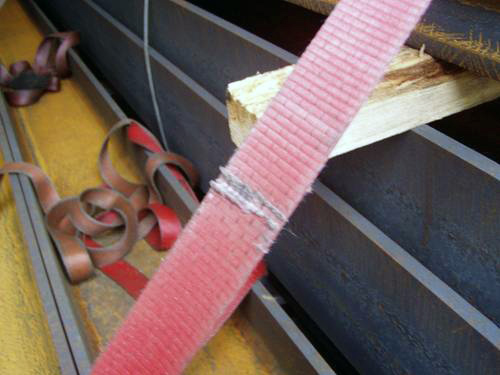
Figure 6 [Frank Horstmann]
So what message shall we take from this photo of the month?
| Belts generate forces that to not act uniformly. Alternating the tensioning side can eliminate this imbalance. | |
| It is possible for belts to provide good load securing, but they have problems with sharp-edged loads. They are useless if suitable corner protection is not used. We recommend that protective sleeves at least are used. Even better protection against sharp edges is available, namely polyurethane U-sleeves through which the belts pass to avoid any direct contact with the load. | |
| Tie-down lashings are complete and utter nonsense with such heavy loads and low coefficients of friction. |
This picture shows a polyurethane sleeve used to protect against sharp edges:
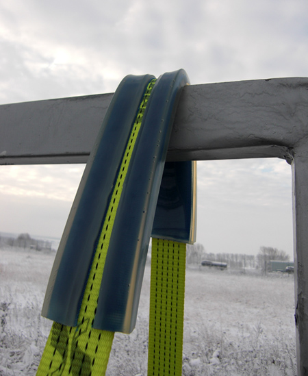
Figure 7 [SpanSet]
So how can a load-securing problem of this nature be solved correctly?
To start with, a truck suitable for transporting steel should be used. This has movable end walls and stanchion systems arranged across the loading area to secure the load to the side. If no such vehicle is available, the end wall must be strengthened with load distribution measures, so that the wall can form part of the load securing strategy as a result of tight-fit loading. Under homogeneous loading conditions, this generally delivers 5,000 daN. Friction-enhancing mats (heavy duty only, of course) increase the coefficients of friction, which always provides added safety.
But beware: If the load is stacked, FE materials must also be placed between the layers of the load, otherwise the good friction values are not present homogeneously throughout the load unit. If belts and wire ropes must be protected if they are used on sharp edges. Chains can be used without protection.
To make life more difficult, many steel cargos are very sensitive and must themselves be protected from the chains.
Such load securing equipment is most effective when used as loop lashings with such heavy loads. The stacked load makes securing with loop lashings more difficult. We would secure the middle stack with two complete loop lashings (two the the left, two to the right). After this has been done, the bottom two steel sections only have to be secured to the middle stack using loop lashings. The use of squared lumber dunnage with a rectangular cross section and FE material glued to both sides considerably facilitates securing with loop lashings.
In our view, the arrangement of the load is not sensible, because the sharp edges of the beams laid on edge would also probably damage the heavy-duty FE material. Beams placed vertically (as seen in the top package in the stack) provide sufficient contact area to prevent the FE material from being damaged and the required effect to be achieved.
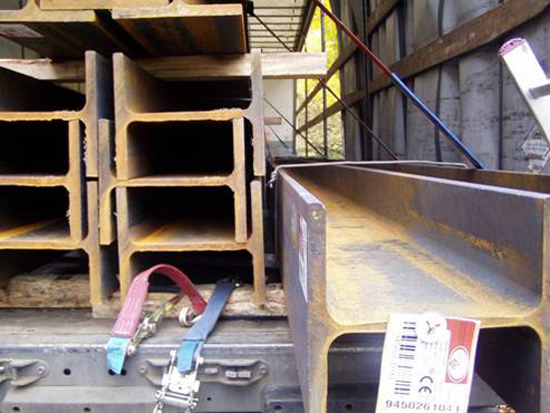
Figure 8 [Frank Horstmann]
The driver had not achieved a tight fit, neither between the parts of the load nor to the front of the vehicle.
The load can also be secured to the front and back using loop lashings. "Head loops" from figure-of-eight burden chains can be valuable here.
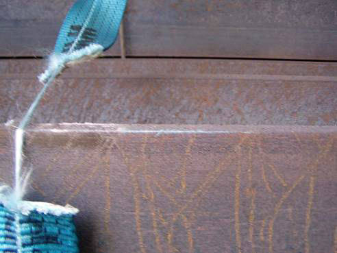
Figure 9 [Frank Horstmann]
Back to beginning