
| Photo of the month – November 2008 | [German version] |
The grass on the other side…
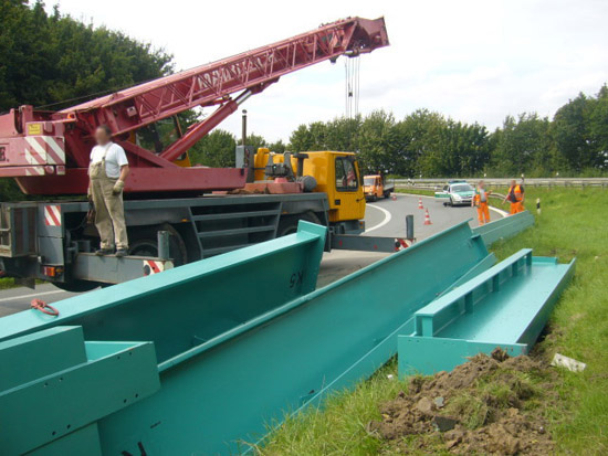
Figure 1 [Wolfgang Jaspers]
Long bends are a good test for lateral load securing, albeit not a particularly demanding one. The consequences of inadequate load securing as shown here provide an excellent example of the "power" of bends and the effect of "good" load securing.
The main aim of November’s photo of the month is to provide an in-depth analysis of the load securing measures that were used. And at the end of the article, we shall discuss a few ideas regarding good load securing.
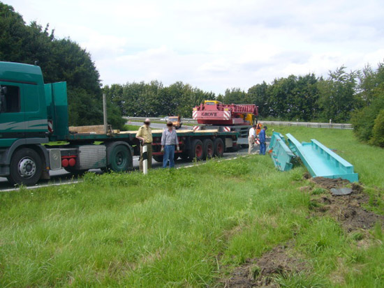
Figure 2 [Wolfgang Jaspers]
But let’s start with the facts. The vehicle was a semitrailer fitted with seven load securing winches. All the winches were fitted to the left-hand side of the vehicle and each provided a 16 mm steel cable to secure the load. Two removable stanchions were placed in the middle of the vehicle in front of the load so that (bottom layer of) the load formed a tight fit against them. A number of pieces of squared lumber were stacked between the stanchions and the load. Assuming that the removable stanchions are sturdy enough, this squared lumber can form a good "artificial" end wall allowing at least the bottom layer of the load to be loaded flush. Below the load and between the layers of the load, square wooden dunnage was also used. I shall return to the treacherous nature of this later.
The load securing measures comprised seven tie-down lashings, friction-enhancing material (wood) and an artificial end wall. At first glance, these conditions not only sound promising – the materials used could have allowed the load to be secured very well in a manner fit for use on the roads.
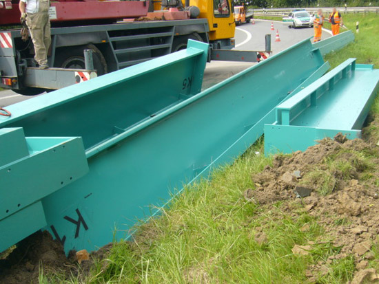
Figure 3 [Wolfgang Jaspers]
The load was made up of steel components that can be described in simple terms as T-beams. The total weight is said to have been 24,000 kg. This means that we can assume that each T-beam weighed around 5,800 kg. The surface of the beams was painted, which means that we would tend toward a value for µ of 0.2 when estimating the friction (wood/steel) rather than a value of 0.3. Depending on the exact nature of the surface, it may well be that a value of 0.2 for µ is generous.
The square dunnage used as intermediate and supporting layers are a well-meant attempt to protect the load, but are a positive hazard with respect to load securing. The square shape means that the dunnage has a cross section similar to that of a circle, which means that it has a tendency to "roll". A practical experiment will give our disbelieving users some astonishing insights.
Experiment:
Take a piece of squared lumber around 9 cm x 9 cm and about 50 cm in length. Place it on a smooth surface and kick the lumber firmly, not forgetting to wear your sturdy shoes. The best results are achieved if you kick the top third of the lumber.
Disclaimer on behalf of GDV:
The GDV accepts no liability for injury of any kind to persons conducting this experiment during the course of the experiment. For those who would prefer to spare themselves the effort of the experiment, we can disclose the results here: Depending on the skill of the experimenter, the lumber will "roll" for several meters.
As for the actual load securing measures:
The idea of achieving a tight fit against an artificial end wall is very good. The idea of securing steel beams with tie-down lashings is nothing short of crackpot. After that rather provocative statement and assessment, those who are interested in load securing and are inclined to delve a little deeper are justified in expecting an explanation. The rest of this article provides just that explanation.
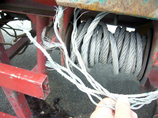
Figure 4 [Wolfgang Jaspers]
Steel cables are surrounded by a mythical aura of invincibility. Steel gives an impression of strength, hardness and durability. Under certain conditions, this is true, but in the context of load securing, steel cable is a big softy at heart. It takes a very dim view of any poor treatment at sharp edges and even the simple act of winding the cable untidily on the winch under load can damage the wire strands. Furthermore, the low elasticity of steel wire means that it is thoroughly unsuitable for use as tie-down lashing material. The only job that wire cables do well, provided that proper edge protection is provided, is direct lashing. If load securing cables on winches are provided for securing loads on trucks, they are generally 16 mm cables with a lashing capacity (LC) of 1,600 through 1,800 daN. These are values that lie below those of the belts commonly used, even though cables and belts cannot be reasonably compared.
A word about pre-tensioning:
Pre-tensioning is vital for tie-down lashings. With belts, it can be assumed that the pre-tensioning force that can be achieved is 10% of the lashing capacity LC, unless information to the contrary is given on the label. In the case of seven cables with an LC of 1,600 daN, this would be 1,150 daN. A maximum pre-tensioning force of 50% of the LC can be assumed. On the tensioning side, this would be 7 x 800 daN = 5,600 daN and on the opposite side 5,600 daN x 0.5 (K value) = 2,800 daN. This means that an absolute maximum pre-tensioning force of 8,400 daN can be achieved with the cables. Great? Well, no, not exactly magnificent. Firstly, this load-securing columnist (with a certain degree of experience) has yet to see a cable on a vehicle on the road (during truck inspections) that came anywhere close to a pre-tensioning force of that magnitude, which is partially due to the fact that loads settle and the cables are not very elastic. 2.) Without adequate edge protection, the cable would have been permanently damaged by the "sharp" edges and could well be ready for scrapping. Let us take a look at the effect of the pre-tensioning if we assume a coefficient of friction μ of 0.2. At the same time, we will use the rather unrealistic pre-tensioning force of 8,400 daN x 0.2 = 1,680 daN. Because we can assume a tight fit to the front (at least for the bottom layer), we shall here only look at the extent to which the load is secured to the side. With a coefficient of friction µ of 0.2, it would still be necessary to secure 0.3 times the weight of the load. This corresponds to 7,200 daN. If we assume a coefficient of sliding friction µ of 0.3, which I consider more than questionable, as explained above, it would still be necessary to secure 0.2 times the weight of the load, in other words, 4,800 daN.
At a value of 0.2 for μ it is possible to achieve a securing force of 1,680 daN with a pre-tensioning force of 8,400 daN and at a value of 0.3 for μ, 2,520 daN with the same pre-tensioning force. In both cases, the discrepancy between the required and actual values is of catastrophic proportions, despite the high pre-tensioning force that we assumed. We shall not take the lashing angle into account here, as the attenuating effect would have been less than 10%.
This experienced load securing columnist also believes that a geometrical peculiarity was also a key contributory factor in this accident. The T-beams were standing upside down and had seven lashings over them. The pre-tensioning force of the tie-down lashings exerted an inward force that pushed the beams together. It can be assumed that the beams tipped in towards each other as a result of the additional lateral acceleration. At precisely this moment, the peripheral dimensions of the load were suddenly reduced and the pre-tensioning forces in the load securing equipment became non-existent. This unfortunate set of circumstances meant that there was nothing stopping the beams from tasting the grass on the verge. The loose cables were no obstacle for the kinetic energy of the T-beams once they had started moving and were simply sliced through.
What steps can be taken to improve a load such as this?
The fundamental problem is the geometry of the T-beams. It is possible to keep them apart by inserting spacers.
Figure 5 [Wolfgang Jaspers]
Figure 6 [Wolfgang Jaspers]
If such spacers prevent the steel beams from tilting towards each other under load, the beams can be secured well using loop lashings. Steel cables are suitable for direct securing using loop lashings. However, they must be available on both sides of the vehicle. Up to now, we have rather ignored the bottom layer. But this also can be secured simply and well using loop lashings and direct securing. We can now take steps to ensure that the load cannot roll by replacing the square wooden dunnage with rectangular, board-shaped dunnage.
By the way, high levels of friction are always desirable, even if the load is secured directly. In the case of steel products, we virtually always recommend mats designed for heavy loads, but even then, care should be taken to ensure that they are not overloaded.
Note for critical readers of the photo of the month column:
We have chosen not to examine the load securing to the front and against the direction of travel in order to keep the column to manageable proportions. For the same reasons, we decided not to discuss the actual friction conditions on the vehicle.
Back to beginning